Pipeline 04
In this exercise you are going to use a common method to define the next system point of pipeline. The method is called Point and Normal.
Before you use this method, you must lock the direction of the pipe. A common method to do that is to route a pipe segment in the right direction and then remove the last pipe part by pressing U.
Do the following:
-
Select Piping > Route pipe.
-
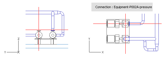
Move the cursor near the second pump's pressure connection.
-
Press Q to lock the cursor to the connection.
-
Press P to connect.
-
Click Yes to accept.
-
For Line, select AA_Water-04.
-
Click Done.
-
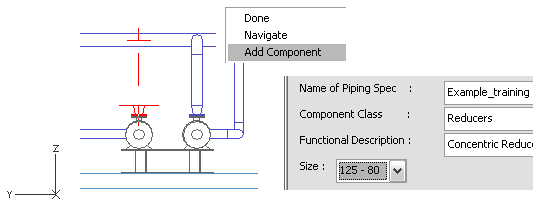
Right-click, and select Add component.
-
For Component Class, select Reducers.
-
For Functional Description, select Concentric Reducers.
-
For Size, select 125 - 80.
-
Click Done.
-
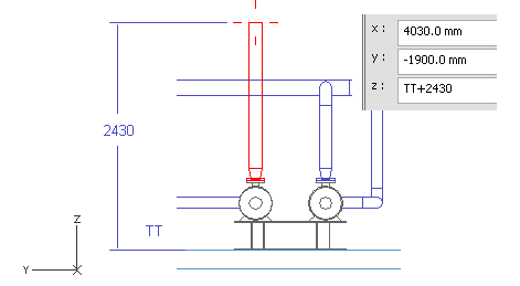
Press Z to set the Z coordinate.
-
For z, enter TT+2430 as the value.
-
Click OK.
-
Press Space.
-
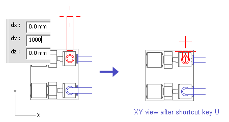
Press D to define the relative movement from the last point.
-
For dy, enter 1000 as the value.
At this point, the specific value for dy does not matter, as long as it is long enough to create an elbow.
-
Click OK.
-
Press Space.
-
Press U to cancel the previous pipe part.
The pipe segment is now removed but the elbow remains, and you are ready to start the Point and Normal method.
Point and Normal method
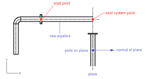
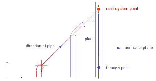
In this section, you locate the next system point using an auxiliary plane. The pipe ends at the intersection of the plane and the centerline of the pipeline. You have to lock the direction of the pipeline. Create an auxiliary plane by specifying a through point (a point on a plane) and a normal vector to the plane.
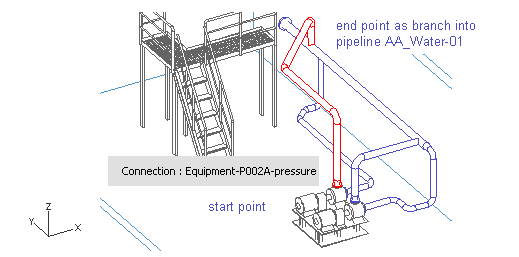
In the picture below, a new pipeline starts at the flange connection of an existing pipeline, so the direction is locked parallel to the X axis. The next system point locates at the auxiliary plane. The plane is parallel to the YZ plane (normal vector is parallel to X axis) and it goes through a point which locates at the centerline of the vertical pipeline.
First, specify the through point.
Do the following:
-
Press R to locate a point and a plane which passes through that point.
-
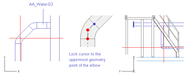
Move the cursor near the 45° elbow of the pipeline AA_Water-03.
-
Press W to lock the cursor to the nearest pipe geometry point (colored blue in the picture below).
-
Press R to release the cursor.
-
Press Space to accept the point.
Next, define the direction of the auxiliary plane.
Do the following:
-
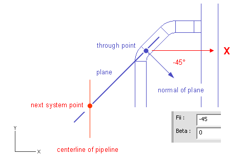
Press S to define the direction of the plane spherically.
-
For Fii, enter -45 as the value.
-
For Beta, enter 0 as the value.
-
Click OK to accept the angles.
-
Press Space to accept the point.
The point locates at the intersection of the auxiliary plane and the direction vector of the pipe segment.
Now, define the direction for the next pipe segment using the spherical method again.
Do the following:
-
Press S.
-
For Radius, enter 1000 as the value.
-
For Fii, enter 45 as the value.
-
For Beta, enter 0 as the value.
-
Click OK.
-
Press Space.
-
Press U to remove the previous pipe segment.
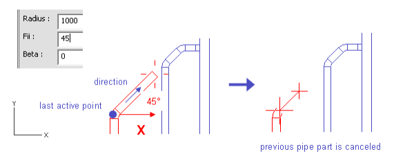
The pipe segment is removed but the elbow remains and the direction is defined.
To finish the Point and Normal method, define the point that the auxiliary plane goes through and the direction of the plane.
Do the following:
-
Press R.
-
Move the cursor inside the pipeline AA_Water-01.
-
Press F11 or Shift+C to lock the cursor to the centerline of the pipe.
-
Press Space to accept the through point.
You have now defined the point that the auxiliary plane goes through.
-
Set the direction of the plane in one of the following ways:
-
Right-click, and select X-axis.
-
Press Alt+X.
-
Press the Right arrow key and Space.
-
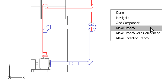
End the routing with a branch.
Do the following:
-
Press Tab to activate the XZ view.
-
Press W to lock the cursor to the last geometry point.
-
Press 6 to enable the cursor to move vertically.
-
Move the cursor inside the run pipe.
-
Right-click, and select Create branch.
The run pipe is highlighted.
If a wrong pipeline is highlighted, press Space until the selection is right.
-
Press Enter to accept the selection.
-
Click Yes to accept the pipe.
You have now routed a pipe using the Plane and Normal method that runs from the second pump's pressure connection to the run pipe using a branch.