New
You can create a new diagram document as follows.
Prerequisites
-
Administrator has defined drawing sheets for diagrams, as described in P&ID Sheets.
-
Optionally, administrator has defined recommended attributes for diagrams, as described in Assigning attributes to object types.
-
Optionally, administrator has enabled synchronization of title box fields and COS document attributes, as described in Synchronizing document attribute and title box values.
Do the following:
-
Do one of the following:
-
Select File > New.
-
Select File > Manage diagrams and then New > Diagram.
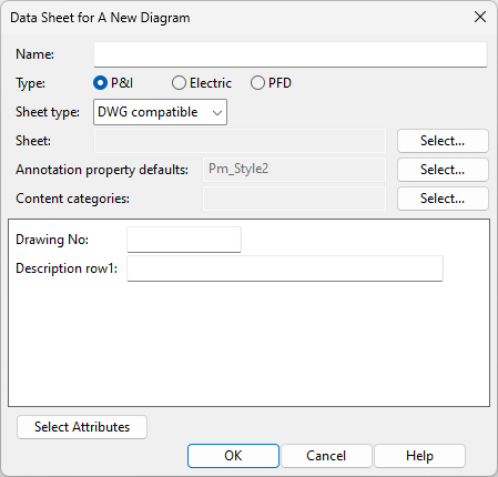
The Data Sheet for A New Diagram dialog opens.
-
-
Enter the following information.
-
Name – Enter a name for the diagram. The name may include spaces but cannot contain certain special characters.
-
Type – Select the type of the diagram.
-
P&I – Select this option for a Piping & Instrumentation diagram. These diagrams describe the operations related to chemical engineering or process engineering at a more detailed level than what PFDs do.
-
Electric – Select this option for a diagram that describes the operations of an electrical system.
-
PFD – Select this option for a Process Flow Diagram that describes the major equipment and the primary process flows in a chemical engineering or process engineering facility at a fairly high level. A flowsheet might show, for example, how materials or objects are moved from one operative point to another for chemical transformation or physical assembly, and what is the flow direction between two consecutive operations.
Important: Only P&I diagrams publish the topological network of pipelines into the 3D model, which allows piping designers to use diagram-based pipe routing assistance. See P&ID integration in 3D routing.
Note: All diagram types publish EPD objects to COS, which allows P&ID to highlight components that exist in the 3D model. See Compare P&ID objects with 3D model.
Tip: You can change the diagram type later from File > Document > Diagram Settings.
-
-
Sheet type – Select the type of drawing sheet to use. The sheet defines aspects such as the page size and the appearance of the title box.
-
NO SHEET – The diagram does not use a drawing sheet.
-
DWG compatible – The diagram uses a DWG-compatible drawing sheet. For more information on this sheet type, see Drawing sheets (DWG).
-
Startup Script – The diagram uses a startup script to create the drawing sheet.
Tip: You can change the sheet type later from File > Document > Diagram Settings.
-
-
Sheet or Script – Click Select to select the DWG sheet or startup script to use.
-
Annotation property defaults – Click Select to select the Annotation Property Defaults to use for this diagram.
Note: The project administrator can select the default Annotation Property Defaults for new diagrams in the Miscellaneous project settings.
-
Content categories – Click Select to select the Content Categories to use for this diagram.
-
Enter values for the attributes of the diagram; click Select Attributes to add or remove attributes.
-
-
Click OK. The new diagram is created and checked out to you. If the Manage Diagrams dialog is open, close it to start editing the diagram.
-
If the diagram uses a drawing sheet, select File > Document > Edit Title Box to define the title box information. The Edit Diagram Title Box Data dialog opens. Users can edit only those fields that administrator has defined as editable. See Edit Title Box.
-
Edit the diagram as required, and save it:
-
Select File > Save locally to save the diagram locally.
-
Select File > Save to COS database to save the diagram in COS.
This action checks the diagram in and then checks it out again. If the diagram uses a startup script and the administrator has configured the PI_CATALOG database table to synchronize the values between the title box fields and the database columns (COS attributes), the title box values will be updated to match the corresponding COS attributes of the diagram.
-
