P&I Diagrams

On the Tools tab, in the External Data group, the P&I Diagrams button opens an object browser dialog that lists the diagrams that have been created with the P&ID application. From this list, you can open a diagram that has been published from P&ID (2024T2 or newer) to Plant Modeller and saved to COS with the option that updates integration. Alternatively, you can open a specific diagram with the Show diagram command described in Managing tree items.
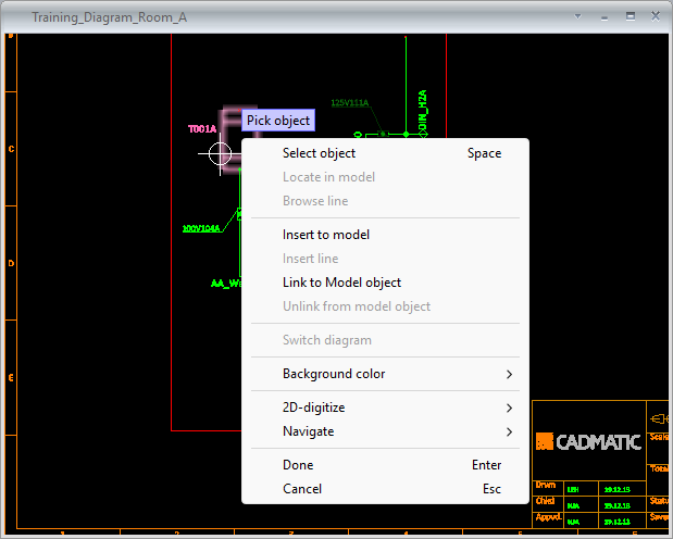
The specified diagram opens in a separate view where you can use the following context-menu commands.
-
Select object – Select an object from the diagram view to access object-specific commands.
-
Locate in model – Closes the diagram view and zooms to and highlights the selected object in the active work view.
-
Browse line – Opens a separate view for browsing the 3D model objects of the selected line.
-
Insert to model – Opens the Select Component Model dialog for inserting a component into the 3D model.
-
Insert line – Allows inserting the selected line into the 3D model.
-
Link to Model object – Allows linking the diagram object to a model object.
-
Unlink from model object – Removes the link between the diagram object and model object.
-
Switch diagram – Opens the other diagram the selected connector is linked to.
-
Background color
-
Select custom – Opens the Drawing Background and Highlight Colors dialog of P&ID for adjusting the diagram background and highlight colors.
-
Reset to default – Restores the default diagram background and highlight colors.
-