Catalog mapping
Catalog mapping refers to rules that automatically link diagram objects to parts in the Corporate Catalog. To create such rules, the project must include a diagram where an armature has a position ID that matches the rule, and the diagram must have been checked in and out once.
In the following example, we use data available in the CADMATIC example project to define a mapping rule where all standard manual valves that use the 'FreshWater' system and 'ISS10BW_1' piping specification will use the 'ASEKO 303' catalog part when inserted into the 3D model.
Prerequisites
- Systems and Lines includes the 'FreshWater' system and 'FRESHW1' pipeline, and both have Used in: set to Plant Modeller and Diagram.
- Piping specifications include the 'ISS10BW_1' piping specification, it is defined to be used for the pipeline 'FRESHW-1', and the Nominal Size is 100.
- The pipeline 'FRESHW-1' includes the standard valve V001.
- The diagram has been checked in and out again.
Creating linking rule objects
You can create new linking rule objects.
Do the following:
-
Select Data tab > Model group > Catalog mappings.
-
In the Manage Linking to Corporate Catalog dialog, select New > Diagram-Catalog Mapping.
-
In the Edit Object Attributes dialog, enter a descriptive name for the rule, and click OK.
-
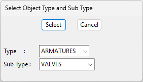
In the Select Object Type and Sub Type dialog, select the diagram object's Type and Sub Type, and click Select.
In this example, we set Type to ARMATURES and Sub Type to VALVES.
-
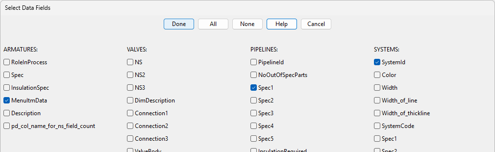
In the Select Data Fields dialog, select the database fields to use in the linking rule.
In this example, we select the following:
- ARMATURES: MenuItmData (V%D2429T2.7.1.01)
- PIPELINES: Spec1 (ISS10BW_1)
- SYSTEMS: SystemId (FreshWater)
So, if a valve object has these three attributes, it will be linked to the Catalog Part that has the specified Part Object ID.
-
Click Done. The new rule is listed in the Manage Linking to Corporate Catalog dialog. You can now add a rule to the rule object, as described below.
Defining linking rules
After creating the linking rule object, define a rule that specifies which data fields to evaluate to link one or more diagram objects to a part in the Corporate Catalog.
Do the following:
-
In the Manage Linking to Corporate Catalog dialog, right-click a rule and select Edit.
-
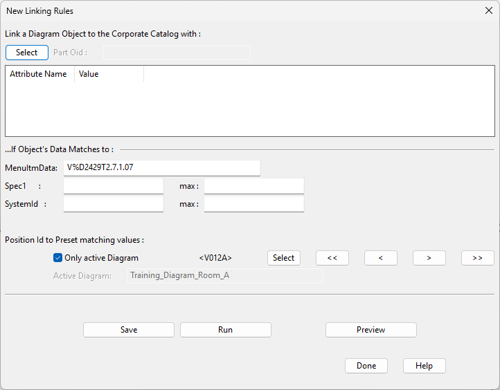
In the New Linking Rules dialog, specify the linking rules:
-
Link a Diagram Object to the Corporate Catalog with – Click Select, select the catalog part to use in Plant Modeller from the object browser, and click OK. The Part Oid field displays the Part Object ID of the catalog part, and the attribute pane displays its attributes.
-
Position Id to Preset matching values – Use the <<, <, >, >> buttons or click Select to select a position ID for the linked valve from checked-in armatures that do not have a Part Object ID link. You can limit the choice list to valves in the active diagram.
-
If Object's Data Matches to – Specify the data to look for in potential candidates. The fields are pre-filled with the values of the selected diagram object—you can modify them as necessary.
- You can leave a field empty to omit it from matching.
- You can use wildcards in string-type fields.
- You can define the minimum and maximum for numeric values. If the minimum is the same as the maximum, then an equality selection is used.
-
-
Click Preview to see a list of diagram objects that match the rules.
-
If you accept the match, click Save to save the rule. The Part Object ID is assigned to the selected valve.
-
You can click Run to apply the rule to other armatures, or perform this action later as described in Running linking rules.
-
Click Done.
Modifying linking rules
You can add a new rule or modify the selection test of an existing rule. Your rule for valves can contain a different part for different sizes or even mapping for ball valves, globe valves, and so on, in the same rule. Thus, you can run the rule for several kinds of valves at the same time.
-
To add a new rule, right-click the rule and select Edit.
-
To modify the selection test of an existing rule, such as changing the spec or adding systems, right-click the rule and select Modify.
When you modify a rule and edit a test, the properties/attributes to test are the fields you selected in step 5 when creating the rule.
Running linking rules
Run the linking rules to link diagram objects to Catalog Parts.
Do the following:
-
In the Manage Linking to Corporate Catalog dialog, right-click the rule to run, and select Run.
-
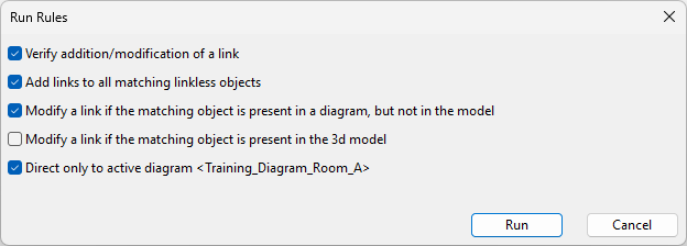
In the Run Rules dialog, select the appropriate settings.
- Verify addition/modification of a link – If selected, you must accept every diagram object to be linked, one by one.
- Add links to all matching linkless objects – If selected, the Part Object ID is assigned to all diagram objects that match the rule and do not yet have a Part Object ID.
- Modify a link if the matching object is present in a diagram, but not in the model – If selected, the Part Object ID is assigned to diagram objects that match the rule and have not yet been inserted into the 3D model, even if another Part Object ID is already assigned to the object.
- Modify a link if the matching object is present in the 3d model – If selected, the Part Object ID is assigned to diagram objects that match the rule, even if they have been inserted into the 3D model. You can use this option to change the Part Object ID of valves already in the 3D model.
- Direct only to active diagram <name> – If selected, the Part Object ID is assigned only to the matching diagram objects in the active diagram. This is very practical if you get diagrams ready for modeling one at a time.
-
Click Run, and accept every object if prompted to do so.
-
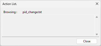
When the linking is complete, the Action List dialog shows all the linked objects, or if there are no matching objects, an empty list is shown. Click Close.