Structural

Structural components contain building instructions that Plant Modeller needs to model structures such as walls, roofs, and windows. The only difference to equipment models (see Equipment) is that a structural component does not have any connectivity info (node points). Therefore, you cannot connect to a node point in a structural component, but you can navigate to features such as corner points, edges, and faces.
Structural components do not have a name, but they have the Structural Position Id (.no) attribute which you can edit with the attribute editor—see Attributes.
Usually structural components are specific to a project and thus stored in the project database, especially when they are modeled without parameters.
Also objects that are modeled as Plates are stored as structural components. See Plate for more information.
Structural components are not used in CADMATIC P&ID integration.
Insert
You can insert a structural component into the 3D model.
Do the following:
-
Optionally, select the system for the new model object from the Model Tree pane.
-
Select Layout tab > Insert group > Structural > Insert (Alt+R).
-
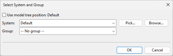
The Select System and Group dialog opens. Define the settings, and click OK.
-
System – Select a system for the model object. You can use the system currently selected in the model tree, select from the drop-down list, pick from another model object, or select from the object browser.
-
Group – Select whether to assign the model object to a group.
-
-
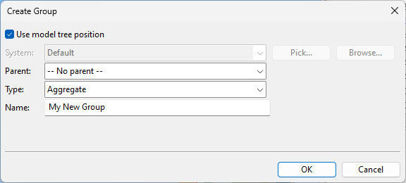
If you chose to create a new group, the Create Group dialog opens. Define the group properties, and click OK.
-
In the Select Component Model window, select the component model to use, and click OK.
-
Navigate to where you want the base point of the structural component to be, and press Enter.
-
In the Edit Attributes dialog, enter a Structural Position Id (.no) for the object.
-
In the Select Component Model window, add another structural object in the same way, or click Cancel to exit the tool.
Model and insert
You can create a new structural component in Component Modeller and then insert it into the 3D model.
Do the following:
-
Optionally, select the system for the new model object from the Model Tree pane.
-
Select Layout tab > Insert group > Structural > Model and insert.
-
The Select System and Group dialog opens. Define the settings, and click OK.
-
System – Select a system for the model object. You can use the system currently selected in the model tree, select from the drop-down list, pick from another model object, or select from the object browser.
-
Group – Select whether to assign the model object to a group.
-
-
If you chose to create a new group, the Create Group dialog opens. Define the group properties, and click OK.
-
Navigate to where you want the component origin to be, and click or press Space to accept the location.
-
In the Select Object Attributes dialog, select the attributes to assign to the object, and click OK.
-
In the Edit Object Attributes dialog, enter values for the attributes you selected to include, and click OK.
-
Use the Component Modeller tools displayed in the ribbon to make the required object geometry, save the component model, and close the Component Modeller tools.


Insert inline
You can insert 3D text as a structural component into the 3D model.
Do the following:
-
Optionally, select the system for the new model object from the Model Tree pane.
-
Select Layout tab > Insert group > Structural > Insert inline > 3D text.
-
The Select System and Group dialog opens. Define the settings, and click OK.
-
System – Select a system for the model object. You can use the system currently selected in the model tree, select from the drop-down list, pick from another model object, or select from the object browser.
-
Group – Select whether to assign the model object to a group.
-
-
If you chose to create a new group, the Create Group dialog opens. Define the group properties, and click OK.
-
In the 3D Text as Structural Component dialog, enter values for Height of text, Thickness of plate (thickness of text), and Text String, and then click OK.
-
Navigate to where you want the lower left corner of the text to be, and click or press Space to accept the location.
-
In the Set Operations dialog, use the Rotate tool to rotate the text, if needed, and then click Close.
-
Create another 3D text in the same way, or click Cancel to exit the tool.
