Navigation map
In CADMATIC Plant Modeller, designers can define 3D spaces that contain for example compartments, flooded volume, or blocks. These 3D spaces, together with planes defined by coordinate references, can be published to 3D models and shown in the 3D model viewer as a map of the model.
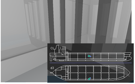
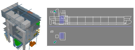
In a ship design project the map is generated by cutting the chosen 3D Space objects from CL (or y = 0 if CL does not exist) to produce a profile picture, and by cutting along each deck level to generate deck layout maps. The nearest deck below the camera is shown as the top view.
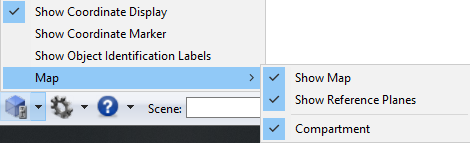
You can show or hide the navigation map and its reference planes from the menu of the Visualization Control toolbar button  . The settings are saved; if you hide the map and close the model, the map is not shown the next time you open the model viewer.
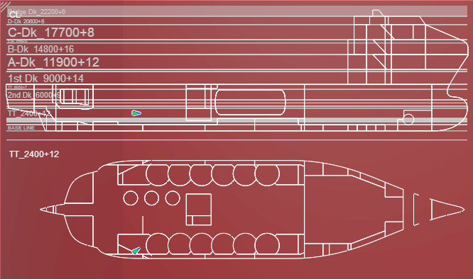
When displaying the map, the small triangles indicate your current camera location and viewing angle within the model. You can click anywhere in the map to change the camera location. If the triangle icon is not filled with color, you are outside the area covered by the map.
You can resize the navigation map by dragging from the triangle in the top-left corner.
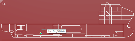
If you have enabled the map's reference planes, the program shows the reference planes on the navigation map as gray lines. It also shows the reference plane names. When you hover over the planes with the mouse, the plane that the cursor is on is highlighted.
If you have not enabled the map's reference planes, the reference plane's name is showed in a tooltip.
The map also shows the clipping box, if you have defined one:
You can resize the map pane by dragging its upper-left corner.