Geometry types
In CADMATIC, there are 15 geometry types that define the shapes of the components that are stored in Dimension Tables.
The geometry type defines:
- Number of node points and their locations.
- Parameters for lengths and angles.
In the table below, you can see the number and the symbolic name of each geometry type, as well as some examples of components that relate to the geometry type.
|
Symbolic name |
Number |
Example components |
|---|---|---|
| DM_GT_PIPE | Type 1 | Straight pipes, beams and plates |
| DM_GT_FLXCURVE | Type 2 | Bends and elbows |
| DM_GT_AUXCOMP | Type 3 | Auxiliary components, like bolt sets, bolts, nuts and washers |
| DM_GT_2P | Type 4 | Flanges, concentric reducers, gaps and gaskets |
| DM_GT_3PDIRFIX | Type 5 | Eccentric reducers and some filters |
| DM_GT_FIXCURVE | Type 6 | Fixed angle elbows and symmetric angle valves |
| DM_GT_TEE | Type 7 | T-pieces and 3-way valves |
| DM_GT_CROSS | Type 8 | Cross pieces |
| DM_GT_LATERAL | Type 9 | Laterals and asymmetric tees |
| DM_GT_VALVE | Type 10 | Valves with handwheels, flowmeters and steam traps |
| DM_GT_ASYMCURVE | Type 11 | Asymmetric elbows and asymmetric angle valves |
| DM_GT_RETURN | Type 12 | 180 degree elbows and some rotameters |
| DM_GT_YPIECE | Type 13 | Y-pieces and 3-way valves |
| DM_GT_PENETR | Type 14 | Penetrations and some unions |
| DM_GT_FLEXCOMP | Type 15 | Components that fall outside the other types, like special geometries and slave parts |
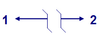
DM_GT_PIPE (1)
Components of this type have two node points. The distance between the points is not fixed.
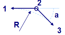
DM_GT_FLXCURVE (2)
Geometry is defined by three points. This is typically used to model elbows which can be cut.
Following dimensions are needed:
- Radius of curvature 'R' (of the arc from point 1 to point 3).
- Angle 'a'. The angle is measured between vectors 1-2 and 2-3 and it can vary.
About flexible curves that use GDL
When pipe components were replaced with piping components in CADMATIC 2019T3, this changed the way how the end point of a flexible curve that uses GDL is calculated, possibly causing the connection point to move so much that the elbow is no longer connected to the pipe from both ends.
When the Dimension Table defines that the elbow uses the DM_GT_FLXCURVE geometry and a GDL geometric shape, then the Dimension Table must have the following dimension attributes:
- "<maximum angle>" as the first "Angle" type dimension attribute, defining the maximum angle of the curve.
- "<angle in GDL>" as the second "Angle" type dimension attribute, defining the standard angle of the curve.
- "MinAngle" as the third "Angle" type dimension attribute, defining the minimum angle of the curve. The name is fixed and case-sensitive.
The minimum and maximum angle parameters are used by the pipe router to ensure that when the user is routing a pipe, the angle of the pipe stays within the specified threshold values.
In projects that have been created before 2019T3, it is recommended to create new GDLs, Dimension Tables and Catalog Parts for flexible elbows, rather than to try to modify the existing ones. Then, the parts in the specifications and any existing piping parts in the model must be changed.
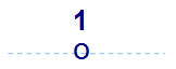
DM_GT_AUXCOMP (3)
Auxiliary components have only one point. These components are used to link branches to pipes in the iso-system.
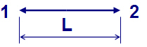
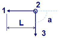
DM_GT_2P (4)
Components of this type have two points.
The distance between the points is required (L). The flow may be blocked (caps, blind flanges, etc.).
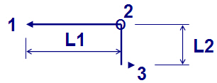
DM_GT_3PDIRFIX (5)
These components have three node points. The direction of flow is maintained; this is used to model eccentric cones. The larger nominal size (DN1) must be in node point 3.
Following dimensions are needed:
- Length. The distance from point 1 to point 2 (L1).
- Eccentricity (offset). The distance from point 2 to point 3 (L2).
DM_GT_FIXCURVE (6)
Fixed curves are specified by three points.
Following dimensions are needed:
- Distance between points 1 and 2. Length 1 – 2 = 2 – 3.
- Angle 'a' between vectors 1-2 and 2-3. The angle does not have to be 90 degrees as in the drawing.
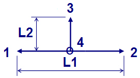
DM_GT_TEE (7)
Tee geometry is specified by four points.
Following dimensions are needed:
- The distance from point 1 to point 2 (L1).
- The distance from point 3 to point 4 (L2).
The point 4 is in the middle point of the vector 1 – 2. (Length 1 – 4 = 2 – 4).
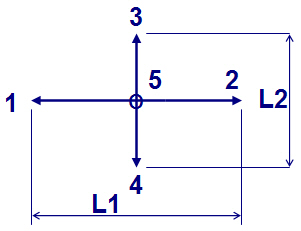
DM_GT_CROSS (8)
The geometry of a cross is specified by 5 points.
Following dimensions are needed:
- The distance from point 1 to point 2 (L1).
- The distance from point 3 to point 4 (L2).
Length 1 – 5 = 2 – 5.
Length 3 – 5 = 4 – 5.
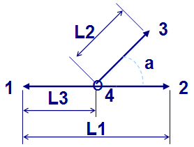
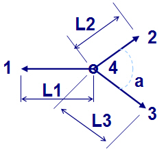
DM_GT_LATERAL (9)
A lateral is specified by four points.
Four dimensions are needed:
- The distance from point 1 to point 2 (L1).
- The distance from point 3 to point 4 (L2).
- The distance from point 1 to point 4 (L3).
- The angle 'a' between vectors 4-2 and 4-3.
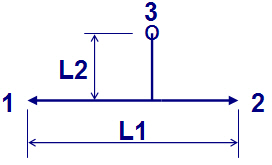
DM_GT_VALVE (10)
Valve geometry is specified by three points. Node 3 is auxiliary point.
Two dimensions are needed:
- The distance from point 1 to point 2 (L1).
- The distance from point 3 to the main line (handle length) (L2).
Geometry doesn't have to be symmetric.
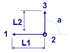
DM_GT_ASYMCURVE (11)
Components are specified by three points.
Three dimensions are needed:
- The distance from point 1 to point 2 (L1).
- The distance from point 2 to point 3 (L2).
- The angle 'a' between vectors 1-2 and 2-3. The angle 'a' doesn't have to be 90 degrees.
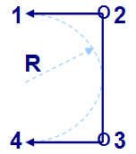
DM_GT_RETURN (12)
Return bend (U-bend) geometry is specified by four points.
Return bend is specified by a single dimension, the radius of curvature (R).
Length 1 – 2 = 4 – 3 and length 2 – 3 = 2 x (1 – 2).
DM_GT_YPIECE (13)
The geometry of Y-pieces is specified by 4 points.
Four dimensions are needed:
- The distance from point 1 to point 4 (L1).
- The distance from point 2 to 4 (L2).
- The distance from point 3 to point 4 (L3).
- The angle 'a' between vectors 4-2 and 4-3. The angle doesn't have to be 90 degrees.
Geometry has to be symmetrical.
DM_GT_PENETR (14)
Geometry is specified by three points. Node 3 is auxiliary point.
Two dimensions are needed:
- The distance from point 1 to 2 (L1).
- The distance from point 1 to 3 (L2).

DM_GT_FLEXCOMP (15)
This geometry type is used with special components, such as vessels, that are not normally considered piping components but should be included in material listings. These components have a variable number of points (up to five). No dimensions are specified. The locations of the points must be specified when the component is inserted into the pipeline.
This geometry type does not have a default isometric symbol for isometric drawings, but you can define a custom symbol for these components, as described in Special 3D iso symbol definition.