Bolt information
In the Project Environment dialog, in [library] > Configuration > Common, the Bolt information configuration object allows the project administrator to specify which bolt set to use for flanges based on pressure rating and face type.
Note: These mappings are used for enabling the visualization of the bolt sets assigned via piping specifications.
Mapping bolt sets to flanged connections
You can specify which bolt set to use in a flanged connection with a specific pressure rating and connection face type.
Prerequisites
-
You have defined the required Bolt Sets.
Do the following:
-
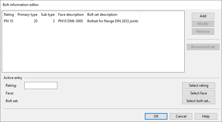
In the Project Environment dialog, browse to [library] > Configuration > Common, and double-click the Bolt information configuration object. The Bolt information editor dialog opens, displaying the existing mappings.
-
To add a new mapping, do the following:
-
Define the following settings in the Active entry pane:
-
Select rating – This button opens a menu for selecting the pressure rating (Metric or ANSI).
-
Select face – This button opens a menu for selecting the type and subtype of the connection face.
-
Select bolt set – This button opens an object browser dialog for selecting the bolt set.
-
-
Click Add. The new mapping is added to the list pane.
-
-
To edit a mapping, do the following:
-
Select the mapping from the list pane.
-
Edit the settings in the Active entry pane.
-
Click Modify.
-
-
To view or edit the bolt set of a mapping, do the following:
-
Select the mapping from the list pane.
-
Click Browse bolt set.
-
-
To delete a mapping, do the following:
-
Select the mapping from the list pane.
-
Click Remove.
-
-
Click OK.
Flange rotation for bolt hole alignment
When a flange is welded to the pipe at the pipe shop, it is necessary to determine how the flange should be rotated so that the bolt holes align with those of the companion flange at the erection site. The rotation angles are computed by Piping Isometrics & Spools when it generates the manufacturing instructions for the pipe. Piping Isometrics & Spools receives the necessary information from Plant Modeller, which adds an extra tag (FBO) to the isometric transfer file for flanges at pipe ends in the following cases:
-
The pipe end is connected to something.
-
The tag 'Ifr' is either undefined for the flange or set to the value 1. This tag is intended to exclude stub end/loose flanges from flange rotation computations. Note that this tag must be assigned to the stub end part, as this part is present in the model; a loose flange is a slave part of the stub end.
The 'FBO' tag includes the following information: the number of holes in the flange, the number of holes in the connected face, a flag that is set if there is a bolt hole on the bolt hole symmetry axis, and the direction of the symmetry axis in plant coordinates.
The number of decimal places used for the flange rotation value can be configured in the options, as described in M-File Output.
Number of bolt holes in a flanged face
To determine the number of bolt holes required for a flanged face with a specified nominal size, pressure rating, and subtype, Plant Modeller first determines which bolt set (dimension table) corresponds to the specified rating/subtype pair, and then extracts the number of bolts (bolt holes) from the corresponding line in the dimension table that matches the nominal size.
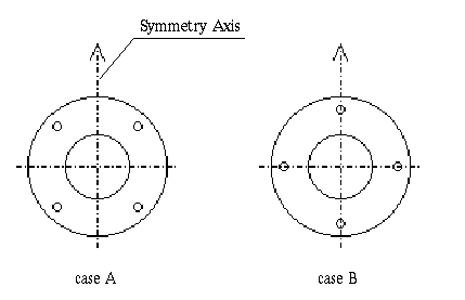
Direction of bolt hole symmetry axis
Connection nodes in component models have a secondary direction. For flanged faces, this specifies the direction of the bolt hole symmetry axis. If this direction is not specified, a default direction is set as follows: if the face direction is up or down, the local y-axis is used; otherwise, it points upward and is perpendicular to the face direction.
Bolt holes can be located in two different ways with respect to the symmetry axis as shown in the figure below. If the last digit in the 'inset_depth' field associated with the node is 0, the orientation is as shown in 'case A'; otherwise, the orientation is as shown in 'case B'.
Flange connected to equipment
The nominal size, pressure rating, and face subtype of the connection node determine the number of bolt holes.
The direction of the bolt hole symmetry axis and the orientation of the bolt holes in regard to the symmetry axis are determined as described in Direction of bolt hole symmetry axis.
Flange connected to standard component
The nominal size, pressure rating, and face subtype of the connection node determine the number of bolt holes. If the pressure rating is 0, the pressure rating from the catalog part is used.
The direction of the bolt hole symmetry axis and the orientation of the bolt holes in regard to the symmetry axis are determined as described in Direction of bolt hole symmetry axis.
Flange connected to flange
The direction of the bolt hole symmetry axis is set as follows: if the pipe's direction is up or down, the y-axis is used; otherwise, it points upward and is perpendicular to the pipe direction. Bolt holes are oriented as described in 'case A' in Direction of bolt hole symmetry axis.
Examples: PN 10;0;NF_D2576M;