Drawing export configuration
Drawing export configuration makes following definitions:
-
Layers when exporting the documents. Layers are grouped to the main menu.
-
Color mappings. In one layer there can be more than one color. Texts and lines can also be mapped to different colors.
-
Linking of attributes. Attributes and values of P&ID database fields can be exported as attributes some formats.
-
Hyperlinks.
Make drawing export configuration before a layer style.
Note: Never delete a layer to which you have referred in a layer style.
How to create new layers
To edit drawing export configuration, in the CADMATIC desktop, select Object > Library and Project Databases. Click the Library, and then click Configuration > Common > Drawing export configuration.
-
On the Main Menu side, click the group where you want to add a layer or click New to create a new group to the main menu.
-
To create a new layer, on the Layer Names side click New. The new layer is located after the active layer.
-
Enter the name of the layer.
-
Enter the properties of the layer.
-
Dxf color settings.
-
Color index in AutoCAD®. Check indices in AutoCAD®.
-
Layer Id. This has to be unique, value smaller than 65000.
-
The default value is the first free number.
-
For default 2D annotations used in drafting style, the value has to be [0,256].
-
There are some fixed layers for sheets.
-
-
Define the color mappings, if needed. There can be defined several colors for texts and lines according to the CADMATIC color and pen indices.
-
Set the color for texts.
-
Set the color for lines.
-
Modify layers
To move existing layer up on the list, on the Layer Names side click Up. To move layers to another group in the main menu, click Move. Then select the layer(s) and click Done. Select the new group for the layer(s) and click Done.
Color Settings
You can define colors for layers as follows:
-
Color Mapping. Use this when you need more than one color per layer. You can set different colors for texts and lines.
-
Use Specified Dxf Color Index.
-
Color by Layer. All the objects on one layer have the same color. This is the recommended main rule.
Linking attributes
Attributes in CADMATIC can be linked to be blocks in AutoCAD®. Following example is for attributes in Plant Modeller:
-
Select Attribute when you want to create a link for attributes.
-
To select the attribute in CADMATIC, click Find.
-
Enter the name for the attribute.
-
Enter the description for the attribute.
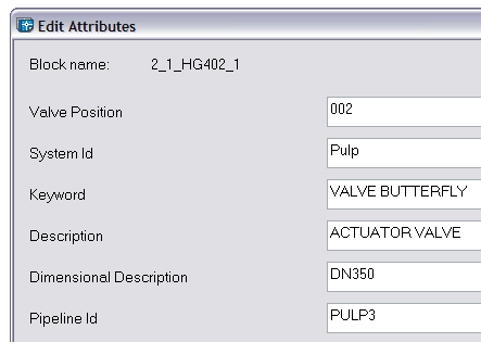
Below you can see an example result in AutoCAD®. The order of the attributes is the same as in drawing export configuration.

Linking P&ID database data to attributes
If you want to link P&ID data to attributes, make following definitions:

Fixed layers for sheets
There are five fixed layers for Plant Modeller drawings and isometric drawings. Don't delete these fixed layers; you can change only the colors and descriptions You can use the same layers also for Diagram sheets.
-
65001. Layer for 2D symbols defined in sheet (logo, sheet frame, etc.).
-
65002. Layer for frames of textboxes, if set to plot frames.
-
65003. Layer for text of text boxes, texts in title boxes, etc.
-
65004. Layer for frames of data tables, material list on sheet.
-
65005. Layer for text of data tables, material list on sheet.