Hull plate material mappings
Hull plate material mappings allow the Multi-pipe penetration tool to select the correct materials for penetrations. They define which catalog parts to use for the plate and sleeve when the hull plate is made of a specific material. These mappings must be defined if their use is enforced in Penetrations.
Prerequisites
- Catalog parts for creating penetrations in hull plates. They must have sizes that are equal to or greater than the thickness of the hull plates.
- You know the hull plate material tag values for which to create new mappings. You can check this for example by viewing the properties of a hull plate with the Query Object Data tool.
Do the following:
-
Do one of the following:
-
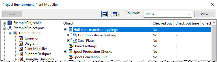
In the Project Environment dialog, go to [project] > Configuration > Plant Modeller, and double-click Hull plate material mappings.
-
In Plant Modeller, select File > Settings > Shared Settings > Piping > Penetrations, and click Edit.
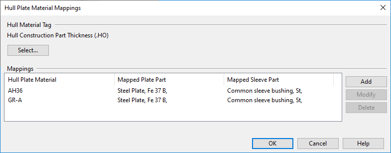
The Hull Plate Material Mappings dialog opens.
-
-
The Hull Material Tag setting defines which COS attribute stores information on materials used by the hull 3D objects. Click Select to select the required attribute from the Select attribute dialog.
-
In the Mappings pane, each row specifies a hull material tag value and the catalog part of the plate and sleeve to use when penetrating the given material.
To create a new mapping:
-
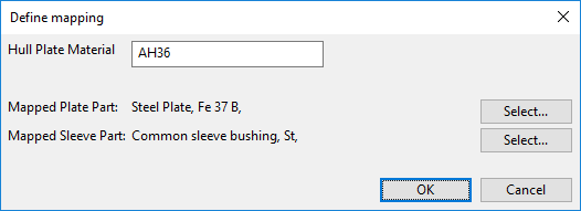
Click Add. The Define mapping dialog opens.
- Hull Plate Material – Enter the hull plate material tag value. The spelling must match exactly the designated attribute value.
- Mapped Plate Part – Click Select to select a Catalog Part for the plate.
- Mapped Sleeve Part – Click Select to select a Catalog Part for the sleeve.
- Click OK.
-
When all required material mappings are defined, click OK to close the mapping tool.