Administrating insulation
Insulation materials have to exist in the library and they have to be assigned to insulation specifications. They cannot be added as "Out of Spec" parts.
-
Insulation objects have dimension tables and catalog parts. They do not need a GDL model, but they can be defined via GDL, too.
-
Connection faces are auxiliary points in catalog parts.
-
Administration assigns insulation materials to functional codes in insulation specification. See Functional codes.
-
Administrator adds the insulation materials and additional materials for the required sizes to the insulation specification.

Common
All connections as auxiliary points in Corporate Catalog.
Note: If insulation material is not defined in specification for a certain functional description, for example for T-pieces, and piping specification defines that this component has to be insulated, the system uses the insulation component defined for pipes to also insulate these components. So in minimum the insulation specification needs to contain one insulation material for pipe.
Geometry types not supported by insulation
- GT_CROSS
- GT_LATERAL
- GT_YPIECE
- GT_PENETR
Standard components (not piping components) made as GT_2P without position ID are not supported by insulation.
Insulation materials
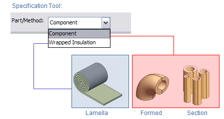
In the Insulation Specification tool there are two different kinds of insulation Part/Method:
- Component – Insulation is listed as length and quantity.
- Wrapped Insulation – Insulation is listed as area.
The component type insulation method is the most common one, and it is used when the insulation material has nominal size (NS) defined. Otherwise, the wrapped type insulation method is used.
Note: In documentation the insulation methods are Lamella (wrapped), Formed Part and Section (component). Currently only Lamella type insulation can be used on ducts.
Insulated parts
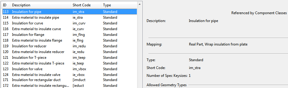
Predefined functional codes for insulation are hard-coded in the system and cannot be modified. If a pipe part is to be insulated, it selects insulation based on the functional codes in the insulation specification.
- im_stra – Insulation for pipes. Parts using geometry type GT_PIPE.
- im_curve – Insulation for curve. GT_FLXCURVE, GT_FIXCURVE, GT_RETURN and GT_ASYMCURVE.
- im_redu – Insulation for reducer. Parts using GT_2P and GT_3PDIRFIX with two key sizes.
- im_flng – Insulation for flange. Parts using GT_2P and bring bolt set in a flange pair.
- im_teep – Insulation for T-piece. Parts using GT_TEE with two key sizes.
- im_vbox – Insulation for valves. Parts using GT_VALVE and Parts using GT_2P and have instrument or valve position.
Insulation for air duct parts modeled as components
Insulation for air duct parts that have been modeled as GDL components can be generated from duct shape information defined in the dimension table, using adjustable shape parameters. The thickness of the insulation is obtained from the insulation specification, just like for straight ducts.
To get insulation geometry from duct shapes, the dimension table of the component must specify the insulation shape to use and formulas for shape parameters. These formulas contain arithmetic expressions that can refer to dimensions via their name. See Dimension table for duct insulation.
Component insulation – dimension tables
For pipes dimension table
- Use geometry type GT_PIPE
- No internal shape needed.
- Thickness of insulation will be taken from the first parameter of type "Diameter" or "Wall Thickness". If both quantity types are used in the same dimension table, the first "Diameter" will be used.
- Use mass/length to define mass.
For curves dimension table
- Use GT_AUX and system will check for the first "Diameter" or "Wall thickness" to build insulation for the curve. No internal shape needed, insulation component will have the same shape as the insulated curve.
- It is also possible to define the maximum angle for the insulation component. Maximum angle will be taken from the first parameter of type "Angle". In that case the system will automatically calculate the amount of insulation components required to insulate one curve. For example, if maximum angle is set to 30°, it will require three components to insulate one 90° curve. In the material list the quantity is set to 3, even though there is only one geometric model.
For flanges dimension table
-
Flanges are insulated by cylindrical insulation box.
-
Use geometry types GT_AUX or GT_2P
-
No internal shape needed. Insulation thickness from Diam or wallt.
-
Bolt set is used for calculation of flange box length.
-
Not all flanges bring insulation box. In a flange pair only one flange brings insulation box that covers both flanges. Flange connected to equipment will bring insulation.
-
When the flange (gasket face) is connected to a standard part then the flange will not bring along insulation. Instead the part (usually valve) brings along an insulation box of its own that covers the flange.
-
Dimension table should include following parameters to properly calculate length of insulation box:
-
Overlap to specify how much the flange box extends along the neighboring part
-
Gap_bolt to specify what is the gap required for bolt in addition to bolt length
-
Gap_nut to specify what is the gap for nuts
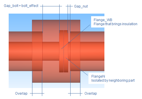
Length of flange insulation box is calculated as
Flange_WB.length + FlangeN.length + 2xOverlap + bolt_effect + Gap_bolt + Gap_nut
where bolt_effect comes from the length of the bolt used in Bolt set for Flange_WB.
-
-
Flange's Catalog Part can have the attribute "Flange insulation thickness from" which can be set to either "Insulated pipe" or "Flange", depending on how insulation thickness is wanted to be calculated.
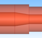
For reducers dimension table
- Use same geometry type as for the insulated part, GT_2P or GT_3PDIRFIX.
- Reducer must have two nominal sizes.
- Use internal shape or GDL. Insulation component doesn't need to have the same geometry as the insulated component.
- Depending on shape used there must be defined at least one diameter type parameter that specifies insulation thickness.
For T-piece dimension table
- T-piece must have two nominal sizes.
- Use same geometry type as for the insulated part if possible.
- Use GDL to define geometry for insulation part.
- If diameter dimension exists AND geometry type is DM_GT_PIPE then section type insulation is assumed.
Insulation is calculated from the first diameter type dimension. Section insulation is added on both main part and run part. If the branch end point would be left within insulated part along main run, then insulation is modeled only with one cylinder along the main run.
For valves dimension table
- Insulation for valve is made as an circular box.
- Use geometry type GT_AUX or GT_2P, no internal shape needed.
- Insulated valve should have at least one dimension of type Diameter.
- Length of box is taken from length of valve. If valve is connected with flanges then the valve insulation box will cover also these and part of the connected pipes.
- Necessary dimensions to compute extra length for the valve insulation box is taken from flange insulation box (Overlap, gaps, bolt effect).
- With symmetric wafer connections the bolt length is taken into account only at the first end of the valve.
- If neighboring parts (flange) have larger diameter than the valve then those are used to compute the outer diameter of the insulation box.
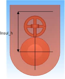
- If the valve itself has a dimension named "Insul_h" then this measures distance from center line to bottom of insulation layer on top of the insulation box. In this case the shape of the insulation box is rounded rectangle.
Wrapped insulation
Dimension tables
- Use geometry type GT_AUX
- No internal shape needed. Insulation will follow the geometry of insulated part with radial expansion equal to insulation thickness.
- No Nominal size. Key dimension is insulation thickness.
- Insulation thickness is taken from first dimension of type Wall thickness.
- Width of insulation is taken from the first dimension of type Length.
- Use mass/area to define mass.
Note: Wrapped insulation cannot be used for flange insulation box.
Wrapped insulation – specification
- Choose functional description and select Wrapped insulation from Part/Method and then Add sizes…
- Select for what nominal sizes the wrapped insulation is to be used.
- Select Catalog part for wrapped insulation and pick the thickness to be used.
Additional material for insulation
-
New object type – Additional material Form
-
Hardwired functional codes for additional material, one for each insulation code.
-
Different types of extra material.
-
Select Add to create new fastening material
-
Give name for new material
-
Select type of material
-
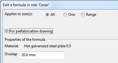
Any formula can be configured so that it is applied when BOM of prefabrication drawing is output:
Note: Don't use type "Cap" in this context since it is for future functionality.
Cover (cladding)
Calculated as the area covering the insulated component
- Add new material
- Possible to select material for all nominal sizes, one nominal size, or a range of nominal sizes
- If selecting range, make sure that ranges doesn’t conflict
- Select component from Corporate Catalog
- Select Plate type object and correct thickness
- Overlap is at the seem when covering circular insulation with one plate, going in the direction of the pipe.
Bind (e.g. wire)
Defined as length per length of insulated component.
- Used also to define tracing.
- Selected material doesn’t need to have any shape. Use GT_AUX for geometry Type
Fasten (e.g. rivets)
Listed as quantity
- Pitch is the length interval in which the fastening material will be added
- Selected material doesn’t need to have any shape. Use GT_AUX for geometry Type
Support
Defined as length per length of insulated component
- Purpose of Support is to keep the insulation on place, especially for long vertical pipes. These kind of supports are normally welded on the pipe
- Select Beam Type object from Corporate Catalog and correct dimension
Insulation pin and screw
These two are applicable for duct insulation only.