Geometry file for document
Geometry is transferred from Plant Modeller to Piping Isometrics & Spools using a temporary file called Geometry Transfer File. The link file is stored into the isometric drawing object. The geometry transfer file has the ".iso" filename extension.
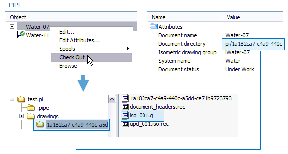
When the isometric drawing is created and the drawing is checked out in Piping Isometrics & Spools, the geometry of the isometric is stored in an ASCII file in the document directory …/.pi/drawings/oid. Geometry files have the ".g" filename extension.
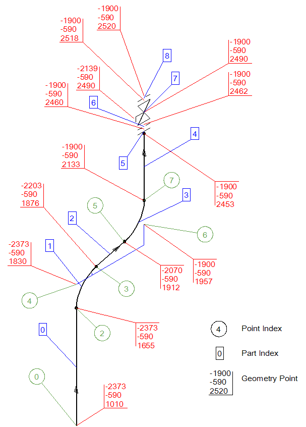
An isometric geometry is a data structure which lists the piping parts in the isometric, defines their locations and all available attributes assigned either for the whole isometric, a part, or geometry point. Also spools are defined in the geometry file.
To be able to make scripts which use the external script function interface of Piping Isometrics & Spools, it is important to understand the basics of the structure of an isometric geometry.
Internally a set of sections and related tables represent the geometry:
-
name
-
dimensions of data table that will follow
-
minimum bounding box
-
parts tables
-
geometry definition indices table
-
geometry points tables
-
link points table
-
header info
-
part tags table
-
extra materials table
-
point tags table
Geometry file example
Name
Water-11; name of the isometric
Dimensions of data tables that will follow
9; number of parts
21; number of geometry definition indices
14; number of geometry points
24; number of link points
1; number of spools
Minimum bounding box
-2373.000000 -590.000000 1010.000000; min x, y, z
-1899.995000 -590.000000 2520.000000; max x, y, z
Part table (section one)
+F_bArR92GqAAZAuGwdUlOm-517 ; part index 0, straight pipe
+Cr25rkMoI9crOuDl0h_CRG-10; part index 1, elbow
+F_bArR92GqAAZAuGwdUlOm-517; part index 2
+Cr25rkMoI9crOuDl0h_CRG-10; part index 3
+F_bArR92GqAAZAuGwdUlOm-517; part index 4
+hlaYMuZIJI_9s8NXsqK3Vm-11; part index 5
+3DsHjzLLGaE8pVStc_uHSW-13; part index 6
+kO6GNJV4HAkziqtZHoivCm-4; part index 7
+3DsHjzLLGaE8pVStc_uHSW-13; part index 8
The format is like this: Part id part name in corporate catalog
Besides real parts there can be invisible auxiliary "parts" which are used to tie the geometry into a fully connected geometry: $AX (=axial), $AD (=along diameter), $B (=bend), $AUX (=auxiliary part).
Part table (section two)
In this table the parts are indices in the same order as in the Part Table (Section One) starting from index 0.
Second numeric value in the row references to the index of Geometry Definition Indices Table. Because first part is a straight pipe part using two geometry points, this part (index 0) uses two points (indices 0 and 1).
1 0 1; symbol Id index 1 (pipe, two geometry points). Part index 0 uses point indices 0 and 1
3 2 1; symbol Id index 3 (elbow, three geometry points). Part index 1 uses point indices 2,3,4
1 5 1; symbol Id index 1 (pipe, two geometry points). Part index 2 uses point indices 5 and 6
3 7 1; symbol Id index 3 (elbow, three geometry points). Part index 3 uses point indices 7,8,9
1 10 1
8 12 1
8 14 1
8 16 1
8 19 1
The format of one row is like this:
-
Sym Id index to Piping Isometrics & Spools symbol table
-
Id to geodefid index to the geometry definition indices table (starts from 0 )
-
Spool id internal spool name (1,2,3 ...)
Geometry definition indices table
2; index 0. Part index 0 uses this point index.
0; index 1. Part index 0 uses this point index.
3; index 2. Part index 1 uses this point index.
4; index 3. Part index 1 uses this point index.
2; index 4. Part index 1 uses this point index.
3; index 5. Part index 2 uses this point index.
5; index 6. Part index 2 uses this point index.
5; index 7. Part index 3 uses this point index.
6; index 8. Part index 3 uses this point index.
7; index 9. Part index 3 uses this point index.
7
8
8
1
10
1
9
10
11
9
12
This table lists indices to the isometry geometry points table. It defines the linking of the geometry type specific points of each part to the global points table i.e. the isometry geometry points table.
The table is a dumped as follows:
-
Each part is scanned
-
The Datamatic geometry type of the part is identified
-
An index to the isometry points table is dumped. One per each point defined by the Datamatic geometry type. E.g. DM_GT_PIPE defines two geometry points.
Geometry points table (section one)
-2373.000000 -590.000000 1010.000000; point index 0
-1900.000000 -590.000000 2460.000000; point index 1
-2373.000000 -590.000000 1654.590000; point index 2
-2203.270000 -590.000000 1875.790000; point index 3
-2373.000000 -590.000000 1830.308000; point index 4
-2069.730000 -590.000000 1911.570000; point index 5
-1899.995000 -590.000000 1957.048000; point index 6
-1900.000000 -590.000000 2132.770000; point index 7
-1900.000000 -590.000000 2453.000000; point index 8
-1900.000000 -590.000000 2518.000000; point index 9
-1900.000000 -590.000000 2462.000000; point index 10
-2139.000000 -590.000000 2490.000000; point index 11
-1900.000000 -590.000000 2520.000000; point index 12
-1900.000000 -590.000000 2490.000000; point index 13
The format of the first section is simple: a table of x,y and z values, one record on a row.
Geometry points table (section two)
1
15
0
2
3
7
9
11
13
18
16
21
23
-1
This is for Piping Isometrics & Spools internal use only.
Geometry points table (section three)
-1
-1
-1
-1
-1
-1
-1
-1
-1
-1
-1
-1
-1
7
This section is obsolete yet needed for compatibility.
Link points table
0 0 5
2 0 -1
4 1 6
3 1 4
2 1 -1
4 1 -1
5 2 -1
3 2 8
6 3 -1
5 3 10
7 3 -1
6 3 12
8 4 -1
7 4 14
1 5 -1
8 5 17
1 6 19
10 6 -1
10 7 22
9 7 20
11 7 -1
10 7 -1
12 8 -1
9 8 -1
This section is for Piping Isometrics & Spools internal use only.
Header info
||
Idn Water-11;pli Water-11;.qM 1;.qN 1;sys Water;.qM 1;.qN 1;.qL 0;.dD test.pm;.pT 1;.d6 PGI76EwvItcP1y2M26JvG0;.pN -7500.0 mm;.pO 60300.0 mm;.pP -5100.0 mm;.pQ 20000.0 mm;.pR 0.0 mm;.pS 20000.0 mm;.dD test.pms;.dG ;.fc INCOMPATIBLE;.fm 5.3.0;.gl TrainingProject.pms;.iA -1703945852;
Header info is to be dumped finally to the h-file when documents are generated.
Part tags table
||
obi 000E2W01C01kpi5Sp4gAIW;.ph 000Bam01C01kpi5Sp4gAIW;spc Example_training;.pd +QM_.0BD_HoAZlR8cyIkqbG;flw -1;spn 001;
obi 000E6W01C01kpi5Sp4gAIW;.ph 000Bam01C01kpi5Sp4gAIW;spc Example_training;.pd +QM_.0BD_HoAZlR8cyIkqbG;flw -1;spn 001;
obi 000EAW01C01kpi5Sp4gAIW;.ph 000Bam01C01kpi5Sp4gAIW;spc Example_training;.pd +QM_.0BD_HoAZlR8cyIkqbG;flw 1;spn 001;
obi 000EEW01C01kpi5Sp4gAIW;.ph 000Bam01C01kpi5Sp4gAIW;spc Example_training;.pd +QM_.0BD_HoAZlR8cyIkqbG;flw 1;spn 001;
obi 000EIW01C01kpi5Sp4gAIW;.ph 000Bam01C01kpi5Sp4gAIW;spc Example_training;.pd +QM_.0BD_HoAZlR8cyIkqbG;flw 1;spn 001;
obi 000EMW01C01kpi5Sp4gAIW;.ph 000Bam01C01kpi5Sp4gAIW;spc Example_training;.pd +QM_.0BD_HoAZlR8cyIkqbG;flw 1;spn 001;
.rt 1;
opT 1;vpo V107;flw 1;.pd +QM_.0BD_HoAZlR8cyIkqbG;spc Example_training;obi 000AqW01C01kpi5Sp4gAIW;
.rt 1;
Part Tags table is a simple list of all tags per each part. There is one row per one part.
Extra material table
||
ext 1;pid +aUh5oynWHWQZ_dv24blJ8m-8;qty 8;gep 1;;
ext 1;pid +YEwoFn_KJnEz9.9U1Owwz0-24;qty 8;gep 1;;
ext 1;pid +aUh5oynWHWQZ_dv24blJ8m-8;qty 8;gep 9;;
ext 1;pid +YEwoFn_KJnEz9.9U1Owwz0-24;qty 8;gep 9;;
Extra materials like gaskets, bolts, nuts and washers are listed in this section of the geometry transfer file.
The format for one record is:
-
pid The Datamatic part id (corporate id - dim table row)
-
qty Quantity
-
gep Index to the geometry points table.
Point tags table
||
gep 12;iso ;ns 150.0;.re 2;pli Water-01;.qM 1;.qN 1;;
This table lists isometry geometry point specific tags. These tags are typically used for passing information about neighbors of this geometry. E.g. messages like "Continues in: xxx" could be labeled in Pipe's annotation module using these tags.
Format of one entry is the standard tag record format. Tag gep is always present and its value is an index to the respective entry in the geometry points table.