Isometric Dimension Style
In the Project Environment dialog, in [library or project] > Document Production > Isometric Dimension Style, the project administrator can define an Isometric Dimension Style configuration, and then take the style into use by selecting it on the Main entities tab of the Automatic Annotation Settings dialog.
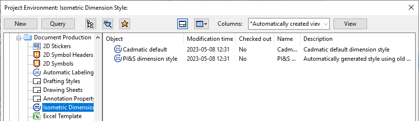
There are two default dimension styles. You can edit an existing dimension style by double-clicking it or by selecting Edit from its context menu.
-
"Cadmatic default" is the default dimension style for isometric drawings created in Plant Modeller, and the settings are described in Edit Isometric Dimension Style. To create a new configuration object of this type, select New > Isometric Dimension Style.
-
"PI&S dimension style" is the default dimension style for isometric drawings and spool drawings created in Piping Isometrics & Spools, and the settings are described in Settings for the Dimension of Isometric and Settings for the Dimension of Spool, respectively.
Edit Isometric Dimension Style
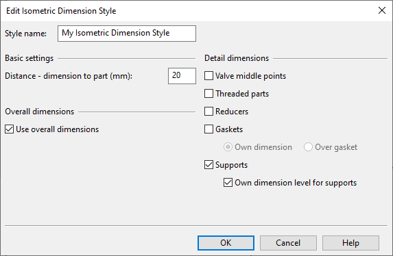
In the Edit Isometric Dimension Style dialog, you can define the following settings for isometric drawings created in Plant Modeller.
Basic settings
-
Distance
Overall dimensions
-
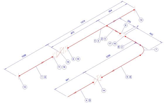
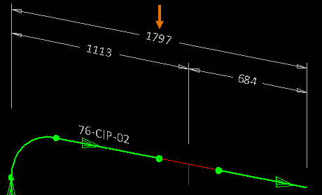
Use overall dimensions – Select this option to show an additional dimension that sums up the individual dimensions along a straight segment. Otherwise, only the individual dimensions are shown.
Detail dimensions
-
Valve middle points – Select this option to dimension valves to their mid-point. If not selected, both ends are dimensioned.
-
Threaded parts – Select whether to dimension threaded connections between parts.
-
Reducers – Select this option to dimension both ends of reducers. If not selected, only the end with the larger nominal size is dimensioned.
-
Gaskets – Select whether to dimension gaskets.
-
Own dimension – Gaskets are dimensioned separately.
-
Over gasket – Parts between gaskets are dimensioned from gasket to gasket. For example, a valve that has a gasket in both end is dimensioned from the outer side of the gasket at one end to the outer side of the gasket at the opposing end.
-
-
Supports – Select whether to dimension supports.
-
Own dimension level for supports – Select this option to place the dimension line of supports at a different height than the other detail dimensions.
-
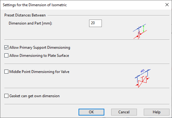
Settings for the Dimension of Isometric
In the Settings for the Dimension of Isometric dialog, you can define the following settings for isometric drawings created in Piping Isometrics & Spools.
-
Dimension and Part (mm) – Define the default distance between a part and its dimension line.
-
Allow Primary Support Dimensioning – Select this option to allow dimensioning of primary supports. Support ID is not required for recognizing the part.
If not selected, primary supports are not dimensioned.
-
Allow Dimensioning to Plate Surface – Select this option to allow dimensioning to the plane where the penetration plate of a multi-pipe penetration with a sleeve meets the target object (such as bulkhead).
If not selected, the dimensioning is first to middle of the sleeve and then to where the penetration plate meets the target object.
-
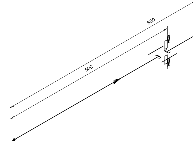
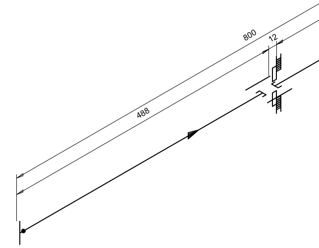
Middle Point Dimensioning for Valve – Select this option to allow dimensioning to the middle point of a valve. Gaskets and flanges are not dimensioned, even if Gasket can get own dimension is selected. This setting can be used when the width of the valve components is not known.
If not selected, the connected gaskets and flanges are dimensioned separately.
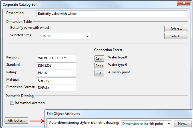
Note: The attribute Auto-dimensioning style in isometric drawing of the valve in the Corporate Catalog must be set to "Dimension to the 4th point".
-
Gasket can get own dimension – Select this option to allow all gaskets to be dimensioned separately.
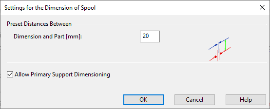
Settings for the Dimension of Spool
In the Settings for the Dimension of Spool dialog, you can define the following settings for spool drawings created in Piping Isometrics & Spools.
-
Dimension and Part (mm) – Define the default distance between a part and its dimension line.
-
Allow Primary Support Dimensioning – Select this option to allow dimensioning of primary supports. (Support ID is not required for recognizing the part.)
If not selected, primary supports are not dimensioned.