Labeling Styles
In the Project Environment dialog, in [library or project] > Document Production > Labeling Styles, the "Labeling Style" configuration objects specify the default visual appearance of drawing labels. The settings do not affect labels whose appearance is defined through Label Definitions.
-
Style Defaults are applied to all labels, unless there are overrides.
-
Label-specific setting overrides are applied to the labels of the specified label definition.
You can create as many labeling styles as needed to control the appearance of labels in different kinds of drawings.
Defining a labeling style
You can create a new labeling style as described below.
Do the following:
-
In Plant Modeller, select File > Environment > All library and project.
-
In the Project Environment dialog, browse to [library or project] > Document Production > Labeling Styles.
-
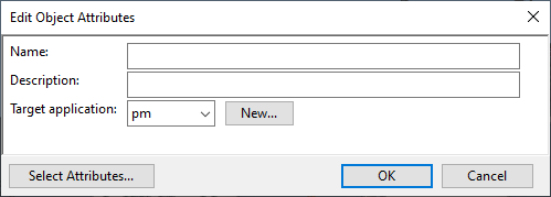
Select New > Labeling Style. The Edit Object Attributes dialog opens.
-
Enter a descriptive name, select the target application (pm = Plant Modeller, pd = P&ID), and click OK.
-
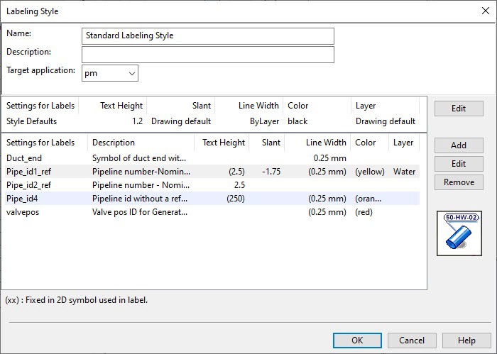
Right-click the new labeling style and select Edit. The Labeling Style dialog opens.
-
Specify the Style Defaults—the default values of the properties described in Visual Settings.
-
Select the Style Defaults row, and click Edit. The Visual Settings for 'Style Defaults' dialog opens.
-
By default, each property is set to Drawing defaults, indicating that the value is taken from the annotation properties of each drawing. To define the value here instead, set the property to Style defaults and specify the value to use.
-
Click OK.
-
-
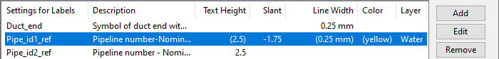
Under Label-specific setting overrides, specify which label definitions are not to use the style default of a given property.
-
Click Add.
-
Select the label definition from the library. (If the labeling style is stored in the project database, you can also select the label definition from the project database.) Then click OK.
-
Select the added label definition and click Edit. The Visual Settings for '<label definition>' dialog opens.
-
By default, each property is set to Style defaults, indicating that the value is taken from the style defaults. To define the value here instead, set the property to Label specific and specify the value to use.
-
Click OK. The overrides table uses the following notation:
-
Fields that display no value use the style default.
-
Fields that display a value use a manually entered value instead of the style default.
-
Fields that display a value in parentheses get their value from the 2D symbol's definition.
-
-
-
Click OK. The configuration object is saved locally.
-
Check in the configuration object to make the changes available to other users.

Visual Settings
In the Visual Settings for… dialogs, you can define the visual appearance of labels through the following properties.
-
Text height – Specifies the height of the label text in millimeters on paper.
-
Oblique angle – Specifies the angle of the label text in degrees from the base position. A positive value tilts the text to the right, and a negative value tilts it to the left.
-
Lineweight – Specifies the lineweight of the lines in the label. The drop-down menu lists the lineweights defined in the Lineweights configuration object.
-
Color – Specifies the color of the label's text and lines. You can pick a color from the list or use the color of the layer.
-
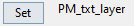
Layer – Specifies the layer on which to place the labels. The Set button opens a menu that lists the layers defined in the layer configuration of the target application.
-
For Plant Modeller, the layers are defined in the Layer configuration.
-
For P&ID, the layers are defined in the Drawing export configuration.
The name of the selected layer is shown next to the Set button.
-
Visual Settings for 'Style Defaults'
These settings are applied to all labels with no label definition specific overrides.
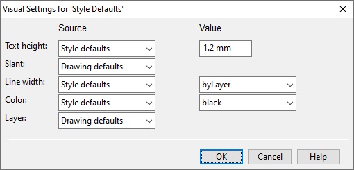
For each property described in Visual Settings, select how to define its default value:
-
Style defaults – Select this option to specify the default value here. When selected, individual label definitions can override the default value in the Visual Settings for '<label definition>' dialog.
-
Drawing defaults – Select this option to get the default value from each drawing's annotation properties.
Visual Settings for '<label definition>'
These settings are applied to the labels of the specified label definition.
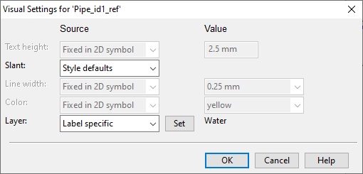
For each (configurable) property described in Visual Settings, select whether to override the style default:
-
Style defaults – Select this option to keep the value defined in Visual Settings for 'Style Defaults'.
-
Label specific – Select this option to override the style default with a different value.