Datum point in support drawings
The datum point of a support can be automatically added to support views and displayed in support drawings. The project administrator can define which 2D symbol to use for this.
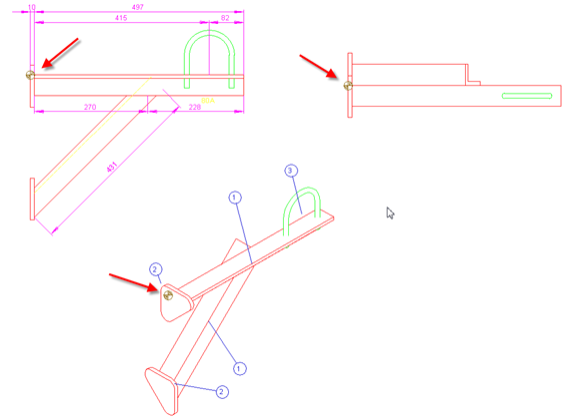
The datum point is located in one of the connected beam ends, and the point is projected to the connected side of the fastening plate along the beam-end normal, if a fastening plate exists. Connected ends of horizontal and vertical beams have priority as the datum point over the ends of diagonal (space-angle) beams.
The algorithm can handle cases where the fastening plate is at the end of a beam (perpendicular or non-perpendicular) or on one of the four sides of the beam end.
The datum point for L-profiles (angle bars) is the outer corner of the L, and for other profile types it is the center of the profile end.
A 0.5° tolerance of parallelity is applied when detecting the connection between the beam and the fastening plate and between the fastening plate and the external structure.
A standard component plate must have a node on both sides and a 'PlateType' attribute. The node numbers must be 1 and 2. Structural plates can also be used.
The external structure to which the support is mounted must be of object type "BEAM", "EQUIPMENT", "HULLCONSTRUCTIONPART", "STANDCMP", or "STRUCTCMP".
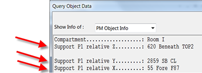
The location coordinates are assigned as attributes to the support group. Therefore, it is possible to show the relative coordinates of the support, in reference to the datum point, in the header of the support drawing.
Attributes for displaying datum points
In the COS object type configuration, 'Model Group' must have four 'Std Support' attributes assigned to it:
| Name | Tag | Type | Details |
|---|---|---|---|
| Std Support Pipe Distances | U23 | String | maximum length 255 |
| Std Support Pipe Sizes | U24 | String | maximum length 255 |
| Std Support Type | U25 | String | maximum length 255 |
| Std Support Sub Type | U26 | String | maximum length 255 |
2D symbol for displaying datum points
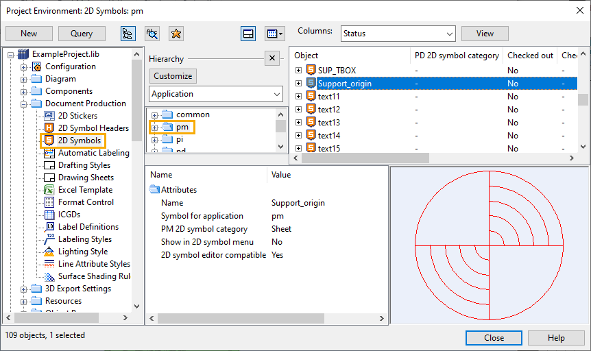
The library or the project database of the current project must contain the Plant Modeller (pm) symbol for the datum point. If the symbol is in the library database, the symbol must be approved for use in the project.
The name of the symbol object must be exactly the same as the name of the symbol function inside the symbol object, and the name must be unique among all the symbols which are approved for use in the current project.
In the CADMATIC Example Project, there is a default datum symbol by the name "Support_origin".
Adding a datum point to drawings
3D designers must activate the datum point functionality in Plant Modeller and select the symbol to use for displaying the datum point in support drawings.
Do the following:
-
In Plant Modeller, select Documents > Drawings, and open any Plant Modeller drawing.
-
On the Tools tab, select Elo Tools > Support Spools Settings. The Support Spool Tool Settings dialog opens.
-
Select the option Add datum point.
-
In the DP symbol field, click Select and select the 2D symbol to be used.
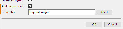
For more information on this dialog, see Define settings for support spool tool.
-
Click OK and close the drawing.