Interfaces
Support Designer has a number of predefined interfaces that allow the 3D designer to model the typically used support constructions with minimal effort. User organizations can also complement the system with their own custom interfaces.
A support interface links together a set of elements, as shown in the picture below.
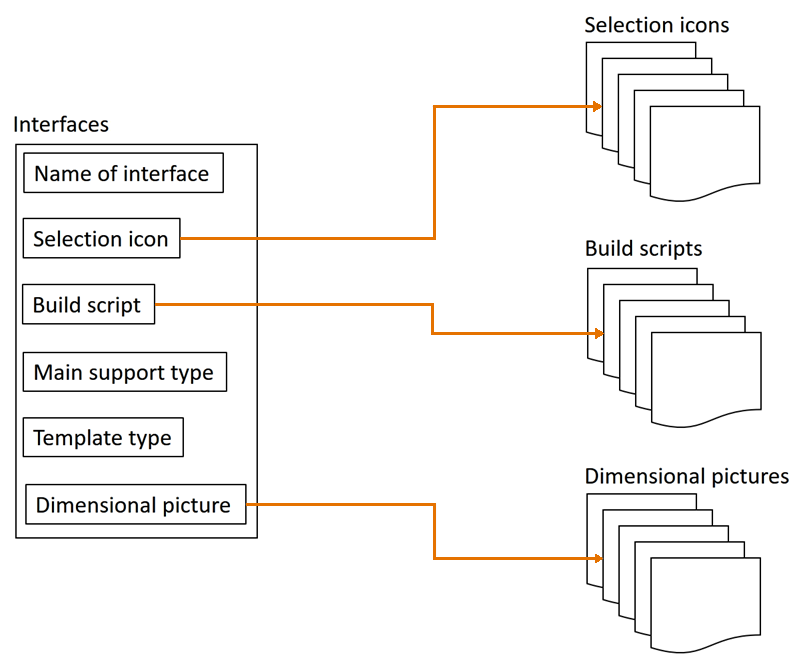
Most importantly, the interface specifies what the supported objects are (air ducts, cable trays, or pipes), what is included in the support construction (primary and secondary supports, or only secondary supports), and how to build the support as a 3D model. At run time, the build script of the interface gets input from the template configuration (Catalog Parts, for example) and the user (3D points, directions) to insert a complete support construction of appropriate size to the designated location.
Interface definition
A support interface consists of the following data fields.
Name of interface
The name of the interface is the key field for identifying the interface so the value must be unique.
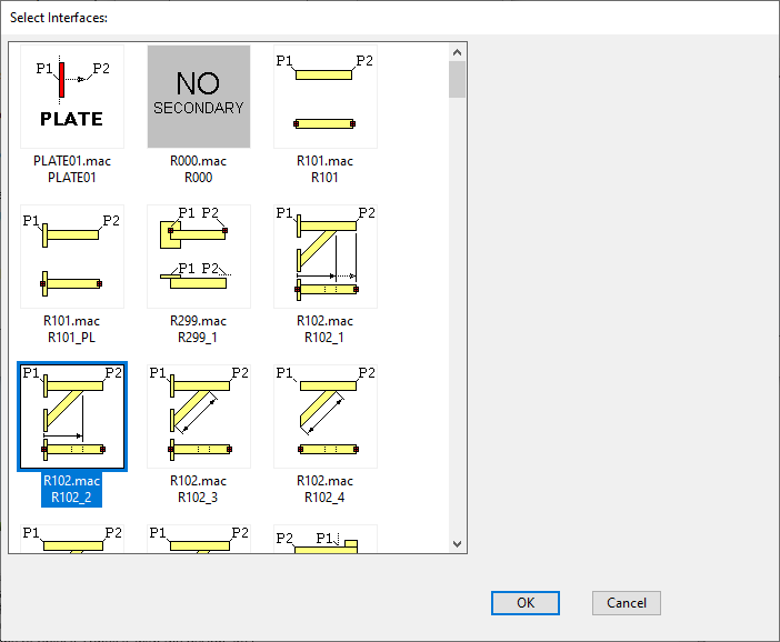
Selection icon
The selection icon of the interface is shown in these situations:
-
Administrator opens a Support Designer configuration object and selects (the interface icon of) a support template to edit its configuration.
-
Administrator opens a Support Designer configuration object, starts creating a new support template, and selects the interface to use for the new template.
-
3D designer opens the Support Designer, starts creating a new support construction, and selects the template to use for the new support.
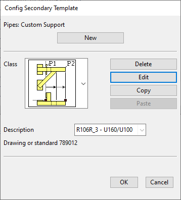
 Show/hide image
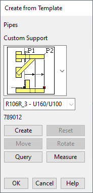
Example of selecting a template for building a secondary support, using the associated build script and the project-specific parameters of the parameter set whose description is "R106R_3 - U160/U100":
Build script
The build script of the interface has two functions:
-
Defines project specific parameters such as dimensions and Catalog Part IDs.
-
Defines a function that builds the support. This is the recipe for building the secondary and/or primary parts of the support, and it uses the following as input:
-
Parameters the project administrator has defined in Support Designer configuration objects.
-
Parameters the 3D designer gives at run time, such as 3D points and directions.
-
Main support type
The main support type of the interface is one of the following:
-
Cable tray support
-
Duct support
-
Pipe support
Template type
The template type of the interface defines what parts are constructed by the build script:
-
Secondary objects
-
Primary and secondary objects (this type is called a "support wizard")
Note: Support wizards are used especially for the rapid creation of simple constructions. Support wizards provide a more automated creation process, but they also require additional project configuration. For details, see Administrating support wizards.
Dimensional picture
The purpose of the dimensional picture of the interface is to show what the project-specific parameters refer to. The bitmap picture is shown when editing a record of a Support Designer configuration object.
An example of a dimensional picture in the template parameter editor is shown below.
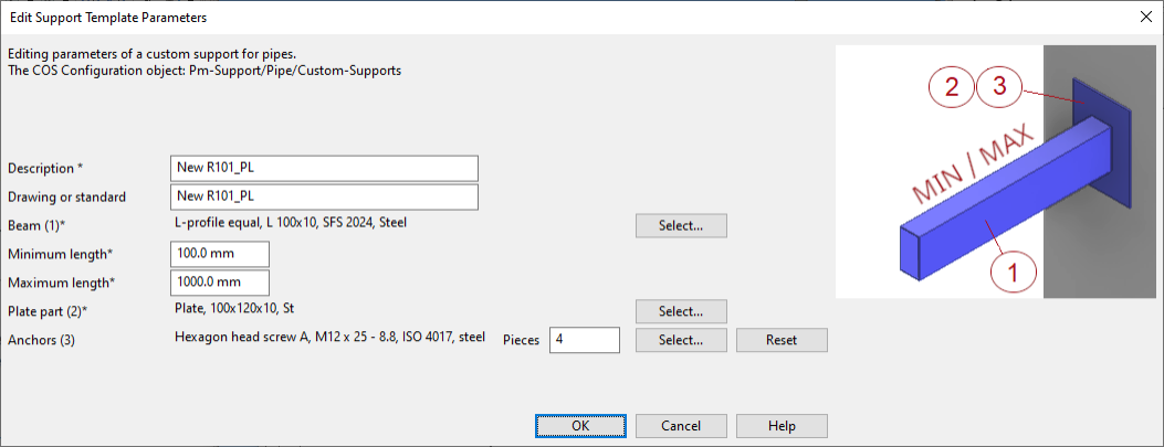
Note: In the editor, mandatory fields have an asterisk at the end of the parameter description text.
Adding custom support interfaces to projects
If a support that is frequently used cannot be built with the default interfaces, you can create your own custom interfaces and custom build scripts for the purpose.
In this example, we show how to add a new interface definition and build script ("EX_101") for secondary supports to the project database.
Prerequisites
-
A custom build script. You can use one of the default build scripts in Resources > Scripts as a basis for your own build script.
-
A custom selection icon (.bmp).
-
(Optional) A custom dimensional picture (.bmp) for showing the purpose of the parameters of the interface.
Do the following:
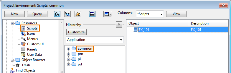
-
In Project Environment > [project] > Resources > Scripts, select New > Script Source to create a new script source COS object, and store your custom build script in this object. Notice that this object has no ".mac" extension.
-
In Project Environment > [project] > Resources > Icons, select New > Icon to create a new icon COS object (type .bmp), and store your custom icon image in this object.
Do this for each bitmap image you want to use in the interface.
-
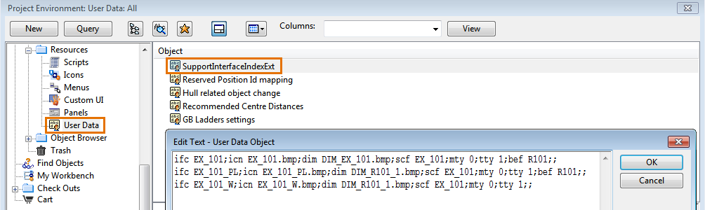
In Project Environment > [project] > Resources > User Data, open the SupportInterfaceIndexExt configuration object, and add your custom Interface definition to this object, using the text editor.
The interface can contain the following tags:
ifc
The name of the interface. The interface creates the secondary support, and if tty=2, then also the primary support.
This name must be unique within the User Data object and in the file %PMS_HOME%\opt\pm\Support\Build\interface\InterfaceIndex.txt. The data in these two sources is combined at run time.
icn
The name of the icon image (bitmap) that is shown when the user is selecting the interface.
dim
The name of the dimensional picture. This is a larger bitmap image which can be shown as a reference when the user is defining the parameters for the new support.
scf
The name of the build script. (In this example, "EX_101".)
mty
The main support type:
• 0 = pipe
• 2 = cable tray
• 4 = duct
tty
The template type:
• 1 = create secondary
• 2 = create secondary + primary (= a support wizard)
bef
In the list of interfaces, the custom interfaces are normally at the end of the list. Their location can be adjusted with the "bef" tag.
-
If "bef" contains the name of a default interface (in the same way as the "ifc" tag is defined in the file %PMS_HOME%\opt\pm\Support\Build\interface\InterfaceIndex.txt), the custom interface is listed before the specified default interface.
-
If "bef" only contains the asterisk character "*", the custom interface is listed first, before the default interfaces.
-
-
Check in the new COS objects, and start testing the interface.