LISEGA LICAD supports
The Support Designer can be integrated with the LISEGA LICAD® software. This allows the Support Designer to construct LISEGA compatible pipe supports such as hangers and clamp bases.
Overview
In Plant Modeller, primary and secondary supports can be constructed using the Support Designer tool, as described in Supports. Only objects whose object type is Standard Component can be used as primary supports. If the Support Designer user selects a primary support that references a LICAD Configuration Template, the program starts LICAD integration and the support is inserted in the 3D model in co-operation with LICAD software. As a result, the Standard Component uses a 3D geometry that has been generated by LICAD and assigned to the primary support object as "embedded geometry".
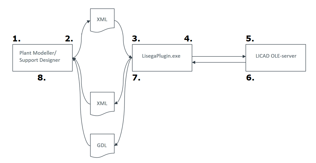
The integration uses a special plugin to pass data between CADMATIC and LICAD, as shown below.
-
The Support Designer user selects a primary support object that uses a LICAD template.
-
Plant Modeller writes data into an XML file and starts the LISEGA plugin.
-
The LISEGA plugin loads the XML file.
-
The LISEGA plugin connects to the LICAD OLE server and passes the data to it.
-
The LICAD OLE server opens a user interface where the user can perform selections, enter and modify data, and complete the building process of the support.
-
The LICAD OLE server passes the data and the 3D geometry of the support to the plugin.
-
The plugin writes the data into an XML file as well as converts the 3D geometry to the GDL format and writes the geometry file.
-
Support Designer loads the data, assigns values to attributes, embeds the 3D geometry in the primary support object, and closes the integration.
To get the LICAD software, do the following:
-
Download the LICAD software from https://www.lisega.de/en/licad/ and install it on your computer.
-
Register the LICAD software at https://www.lisega.de/en/licad/registration/,
-
Start the LICAD software and enter your personal registration code.
Concepts
The CADMATIC—LICAD integration requires a LICAD OLE server to be installed in the same computer as CADMATIC.
In the LICAD software, each support type has a configuration number that identifies the support and dimensional parameters that define the shape of the support. You can find the configuration numbers and the dimensional parameters in the LICAD manual: in the LICAD V11 manual, they are listed in chapter "10.2 The supports configurations (symbols)".
In CADMATIC—LICAD integration, the LICAD configuration of a particular support is defined in the LicadConfigNo COS attribute.
In CADMATIC, a LICAD configuration template represents a group of LICAD configurations whose main dimensional parameters are the same. That is, the LICAD manual lists a number of static (68), dynamic (8), and "cold" (18) LICAD configurations which CADMATIC manages by allocating them into a smaller number of configuration types.
In Plant Modeller, there must be one Catalog Part/Dimension Table/GDL per configuration template. The GDL implements the dimensional parameters via instance parameters, and the designer can define the exact size of a specific LICAD support when inserting the support in the model.
In CADMATIC—LICAD integration, the configuration template of a particular support is defined in the LicadConfigTemplate COS attribute.
CADMATIC considers a primary support object to be "LICAD enabled" if the object references a Dimension Table which has the attribute LicadConfigTemplate assigned to it. This means that the object can be used as a primary support template in the integration.
CADMATIC considers a primary support object to be "LICAD integrated" if the LICAD software has assigned the attribute LicadDrwNo to the support object.
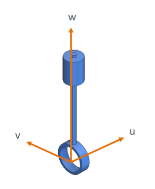
CADMATIC defines the geometry of a Standard Component in local, right-handed u, v, w coordinates.
CADMATIC defines the location of an object in a Plant Modeller design area in global, right-handed x, y, z coordinates. When a designer inserts a support in the 3D model, the object's location and orientation are stored in the project via the global location of the origin point of the component model and the global directions of the local u and v axes.

LICAD, on the other hand, uses a local, left-handed coordinate system.
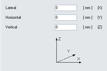
This means that the CADMATIC u-axis corresponds with the LICAD "horizontal" direction, v-axis corresponds with the (negative) LICAD "lateral" direction, and w-axis is the same as the LICAD "vertical" direction.
In Plant Modeller the user defines movements in CADMATIC global directions. These values are stored in attributes (see Support COS Attributes) and transformed into local LICAD movements which are shown in the user interface (read-only).
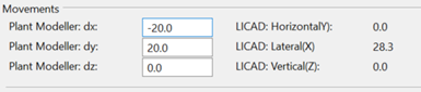
So, when defining movements, first there is transformation from CADMATIC global to CADMATIC local, then from CADMATIC local to LICAD local. When the Support Designer user starts an integration session, the values are given as input to the LICAD software. When the LICAD user interface is closed, the LICAD values are converted back to CADMATIC global values, the user can review the differences, and then either accept or cancel. If the user cancels, nothing is updated in Plant Modeller and the LICAD database and the CADMATIC database are out of sync until the user runs another integration session and accepts the returned values.
Setting up
Project administrator must set up the CADMATIC–LICAD integration by performing the following:
Define attributes
Starting a LICAD integration session with Support Designer checks the following attributes. The names and the types of the COS attributes must be correctly defined in the COS schema; the abbreviations do not matter, the Support Designer identifies the attributes via their names.
These COS attributes typically get their values from piping stress analysis or piping design. The attributes can be stored to a primary support before the support is integrated with LICAD or defined on-the-fly in the integration.
|
Name |
Type |
Values |
Description |
|---|---|---|---|
|
String |
|
The "position ID" of a hanger support. The designer defines the value in Support Designer before integrating the support with LICAD. The value functions as a key to the support drawing and the data record in the LICAD database. |
|
|
Integer |
0 / 1 |
|
|
|
Floating point (Length) |
|
Load (kN). |
|
|
Coded enumerated |
1: Static 2: Cold 3: Dynamic |
LICAD load type. |
|
|
SupportMovNeg SupportMovPos |
Floating point (Length) |
-1000000 – 1000000 |
Vertical movement (mm) of snubber type supports. |
|
SupportMovX SupportMovY SupportMovZ |
Floating point (Length) |
-1000000 – 1000000 |
Movement (mm) in global x, y, z directions of Plant Modeller. |
The values of these COS attributes are defined or generated in LICAD when the primary support is integrated with LICAD and then stored in the primary support object.
|
Name |
Type |
Values |
Description |
|---|---|---|---|
|
Integer |
A three-digit number n1n2n3, where n1 is the load type code (1:static, 2:cold, 3;dynamic) and n2 and n3 form the LICAD configuration symbol, as described in chapter 10.2 of the LICAD manual. |
LICAD configuration number. |
|
|
Coded enumerated |
1: Simple suspension for horizontal pipes 2: Clamp base / pipe shoe for horizontal pipes 3: Trunnion for horizontal and vertical pipes 4: Single beam trapeze for horizontal pipes 5: Single beam trapeze for vertical pipes 6: Double beam trapeze for horizontal pipes 7: Double beam trapeze for vertical pipes |
Specifies the LICAD configuration template. |
|
|
String |
|
(Optional) Defined by the user in LICAD. |
|
|
String |
|
A key to support drawing and data record in LICAD database. Generated by LICAD. |
For general information on COS attributes, see Attributes.
The GDL object used by the primary support object must have the following attribute.
|
Name |
Tag |
Type |
Values |
Description |
|---|---|---|---|---|
|
_T0 |
String |
A list of tag records. If the tag records are to be included in a BOM report or on the drawing sheet, then customized m-file processing will be used to implement that. A string format list of tag records can be loaded into an array of tag records via a single call to the DM_SCAN_TAGRECS_FROM_STRING script extern. See the tag definitions in the file LicadBomTags.h. MMT_TAG_LISEGA_BOM only exists if the Standard Component uses embedded LICAD geometry. See the header file include\LicadBomTags.h. |
The LICAD "BOM" of the support: generated by LICAD when the support is completed there. |
Define GDLs
In the Component Modeller application, define a GDL for Standard Component, one per support type defined in the LicadConfigTemplate attribute.
Typically, one or more instance parameters are needed in the GDLs. Instance parameters need to match the dimensional parameters of the targeted LicadConfigTemplate value.
You can probably find a suitable GDL from the CADMATIC example project.
Define dimension tables
In the Project Environment dialog, in [library or project] > Components > Catalog Parts > Dimension Tables, define a Dimension Table for each GDL.
Define the dimensions that correspond with the referenced GDL and assign a value for the LicadConfigTemplate attribute.
You can probably find a suitable Dimension Table from the CADMATIC example project.
Define catalog parts
In the Project Environment dialog, in [library or project] > Components > Catalog Parts > Catalog Parts, define a Catalog Part for each Dimension Table.
You can probably find a suitable Catalog Part from the CADMATIC example project.
Define piping specification setups
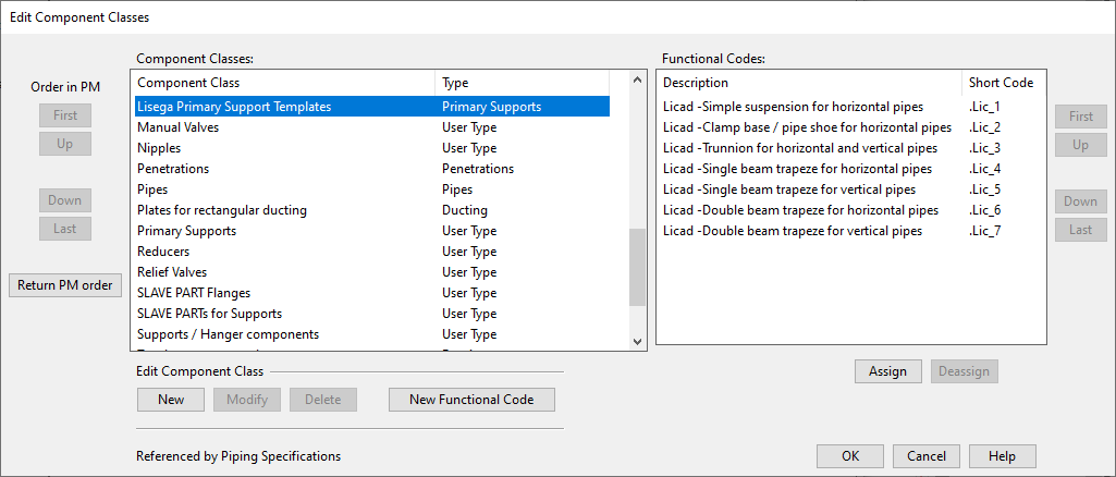
In the Project Environment dialog, check that there is a Component Class that references Functional Codes for LICAD supports.
Do the following:
-
Check that [project] > Configuration > Common > Functional codes contains a functional code for each configuration template defined in the LicadConfigTemplate attribute. Add the setup if it is missing.
Description
Short Code
Type
Licad -Simple suspension for horizontal pipes
.Lic_1
Standard
Licad -Clamp base / pipe shoe for horizontal pipes
.Lic_2
Standard
Licad -Trunnion for horizontal and vertical pipes
.Lic_3
Standard
Licad -Single beam trapeze for horizontal pipes
.Lic_4
Standard
Licad -Single beam trapeze for vertical pipes
.Lic_5
Standard
Licad -Double beam trapeze for horizontal pipes
.Lic_6
Standard
Licad -Double beam trapeze for vertical pipes
.Lic_7
Standard
-
Check that [project] > Configuration > Common > Component classes contains the component class "Lisega Primary Support Templates" and that it references the LICAD functional codes. Add the setup if it is missing.
Update piping specifications
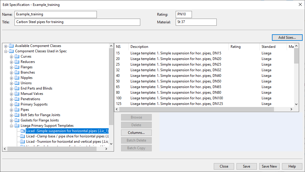
In the Project Environment dialog, in [library or project] > Specifications > Piping Specifications, open the required specification and add the required Part Sizes to it.
Customize m-file post-processor
If the LICAD BOM is needed in reports or in Plant Modeller drawings, then customize the m-file post-processor script as needed. See MMT_TAG_LISEGA_BOM.