Import

On the Insert tab of Component Modeller, the Import group includes the following tools.
Import file

Select Insert tab > Import group > Import file to import a 3rd-party component model from a file.
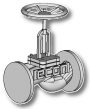
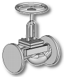
Depending on the source program, the imported model can contain parts that are never visible outside the component model. For example, the model of a machine can be very detailed also on the inside, whereas for designing the floor layout only the outer appearance is needed. Removing the invisible parts can make the component model lighter and reduce the possibility of Plant Modeller slowing down because of overly detailed equipment models. Therefore, after the import, the program runs the Delete interior command to inspect whether the imported geometric primitives contain removable parts.
Unless there is a reason to see, for example, the internals of a machine in a cut-away view, you should accept the invisible parts to be deleted. If you are not sure what those parts are, you can import the model as is, use the Delete visible command to delete the outer parts, and then re-import the model to restore its outer parts and remove the inner parts.
Note: The only way to restore the deleted interior or exterior of a component model is to re-load the model from the original source file.
STEP and STEP-convertible files
You can use the Import file command to import STEP files. Additionally, other types of files that can be imported through intermediate conversion to the STEP application protocol 214 (AP214) format are also supported.
|
Format |
Extension |
|---|---|
|
ACIS CAD SAT |
|
|
AutoCAD DXF |
|
|
Autodesk Inventor |
|
|
CATIA V5 |
|
|
Parasolid |
|
|
Solid Edge |
|
|
SOLIDWORKS |
|
|
STEP |
|
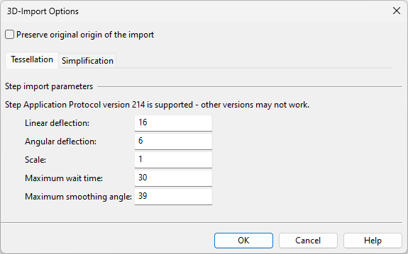
After selecting the file to import, the 3D-Import Options dialog opens for defining the import parameters.
-
Preserve original origin of the import – Select this option to keep the imported origin of the component model. If not selected, the program computes a new origin.
-
Tessellation – See Tessellation tab.
-
Simplification – See Simplification tab.
DWG files
You can use the Import file command to import component models from DWG files.
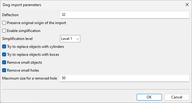
After selecting the file to import, the Dwg import parameters dialog opens for defining the import parameters.
-
Deflection – Specify the maximum difference between the actual curve or surface and the tessellated curve or surface within the current viewport.
-
Preserve original origin of the import – Select this option to keep the imported origin of the component model. If not selected, the program computes a new origin.
To use the following options, your environment must have the separately installed CADMATIC Simplifier tool and a separate license.
-
Enable simplification – Select this option to enable simplification.
-
Simplification level – Select the simplification level.
 Show/hide details
Level 1, least simplification
Level 2, moderate simplification
Level 3, most simplification
-
Try to replace objects with cylinders – Select this option to replace approximately cylindrical bodies with a cylinder.
Turning this off can slightly decrease the processing time.
-
Try to replace objects with boxes – Select this option to replace approximately box-shaped bodies with a box.
Turning this off can increase the processing time and the workload of the other tools.
-
Remove small objects – Select this option to remove bodies whose bounding box is small.
-
Remove small holes – Select this option to remove holes whose entry/exit size is less than the threshold value, regardless of cross section or form.
Maximum size for a removed hole – Specify the threshold value for removing small holes.
JT files
You can use the Import file command to import component models from JT files.
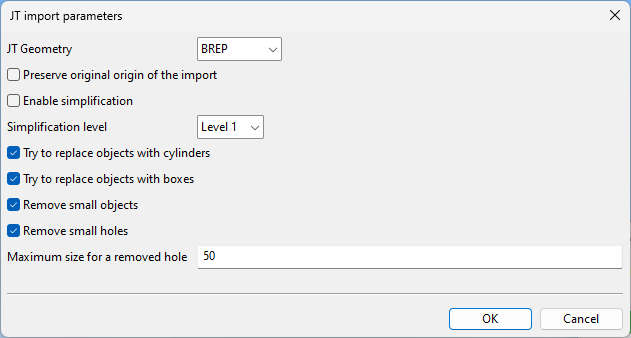
After selecting the file to import, the JT import parameters dialog opens for defining the import parameters.
-
JT Geometry – Specify how object geometry is generated in JT import. This can be set to one of the LOD levels in the JT file, or you can choose to tessellate the XT brep geometry present in the JT file.
-
Preserve original origin of the import – Select this option to keep the imported origin of the component model. If not selected, the program computes a new origin.
To use the following options, your environment must have the separately installed CADMATIC Simplifier tool and a separate license.
-
Enable simplification – Select this option to enable simplification.
-
Simplification level – Select the simplification level.
Show/hide details
Level 1, least simplification
Level 2, moderate simplification
Level 3, most simplification
-
Try to replace objects with cylinders – Select this option to replace approximately cylindrical bodies with a cylinder.
Turning this off can slightly decrease the processing time.
-
Try to replace objects with boxes – Select this option to replace approximately box-shaped bodies with a box.
Turning this off can increase the processing time and the workload of the other tools.
-
Remove small objects – Select this option to remove bodies whose bounding box is small.
-
Remove small holes – Select this option to remove holes whose entry/exit size is less than the threshold value, regardless of cross section or form.
Maximum size for a removed hole – Specify the threshold value for removing small holes.
Other files
You can use the Import file command to import component models from 3DC, 3DD, 3DDX, 3DP, CDI, IFC, and OBJ files (planar polygon geometry only).
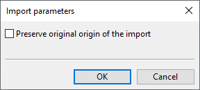
After selecting the file to import, the Import parameters dialog opens for defining the import parameters.
-
Preserve original origin of the import – Select this option to keep the imported origin of the component model. If not selected, the program computes a new origin.
Import GDL

Select Insert tab > Import group > Import GDL to import an existing GDL object (Standard Component, Structural Component or Equipment) to the current component model.
If the GDL object has parameters, you are prompted to define their values (they can be GDL expressions).
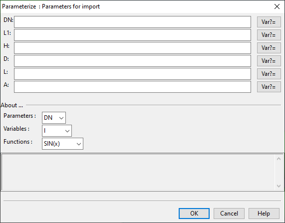
After the initial import, you can translate and/or rotate the imported primitives.