Using nodes to define bolt hole locations
Plant Modeller supports air ducts that have rectangular flanges constructed from beams. When such flange is connected to an industrially manufactured air duct component, the nodes in that component must be able to specify the locations of bolt holes, so that the correct bolt information can be shown in the prefabrication drawing of the constructed flange.
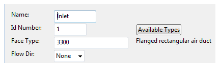
Component Modeller allows bolt hole locations to be specified with Insert > Node. The face type must be "Flanged rectangular air duct".
 .
.
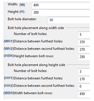
The parameters to be defined are shown in the picture below. The number of columns is five and the number of rows is three in the picture.
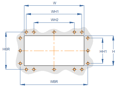
In both width and height directions, the user specifies the bolt hole count and the distance between the furthest and the second furthest bolt holes. The distance between the second furthest bolt holes will then be evenly divided by the bolt holes.
Note: If the distance between the holes is set to 0, the holes are evenly spaced.
Note: Inset depth can only be set with connection types DM_CT_FLGWELD, DM_CT_FSOCKETW and DM_CT_FTHREAD.