Compare P&ID objects with 3D model
The integration between Plant Modeller and P&ID allows Plant Modeller to automatically link objects that have the same position ID in P&ID and in the 3D model. This linking occurs when the objects are first published from P&ID to 3D and then inserted to the 3D model with Plant Modeller. If an object is first inserted to the 3D model and only after that published from the diagram, then the Plant Modeller user must link the objects manually.
Objects that are linked to the 3D model can detect certain differences in the data. If the diagram is edited after the objects already exist in the 3D model, the P&ID user can check and resolve the data to match the data in the 3D model. If the data is correct in P&ID but not in Plant Modeller and the diagram has been published to 3D, then the differences must be resolved in Plant Modeller, as described in Compare objects.
Compare with 3D model
On the Tools tab, in the Model group, selecting Compare Objects > Compare with 3D Model opens a dialog that shows the items that have an integration link to the 3D model and have differences in the data between the 3D model and P&ID.
Differences that are shown are:
- Integration attributes with modification rights both in 3D Model and in P&ID
- Difference in selected component model
- Difference in system for equipment
- Difference in system and pipeline for valves
- Nominal sizes of valves for first two key dimensions
- Name of cable
- Material of cable
- System of cable
- Interference class of cable
- Maximum length of cable
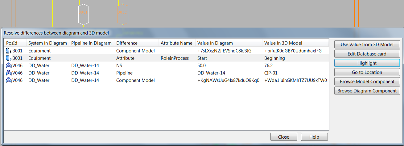
Each difference is shown on a separate row. Differences can be sorted by columns. Multi-selecting of list items is possible. If P&ID user knows that the value is correct in P&ID, the difference must stay in the list until the respective command is used in 3D and the Plant Modeller user resolves the difference.
- Use Value from 3D Model replaces the value in the diagram with the value from the 3D model. Multiple differences can be resolved by multi-selecting.
- Edit Database card opens the database for defining an alternative value.
- Highlight highlights the object in the active diagram.
- Go to Location works only for a single selected object and moves the cursor to the object in the diagram.
- Browse Model Component and Browse Diagram Component show the component that in the 3D model or in P&ID, respectively, was selected from the library.
Note: File > Options has a shared project setting where Compare with 3D can be automatically run when checking out/in P&ID or before publishing to 3D.
Highlight
With highlight command user can view what objects are already modeled in 3D. These commands only work properly if the integration setting is on and the objects have a link between 3D and P&ID.