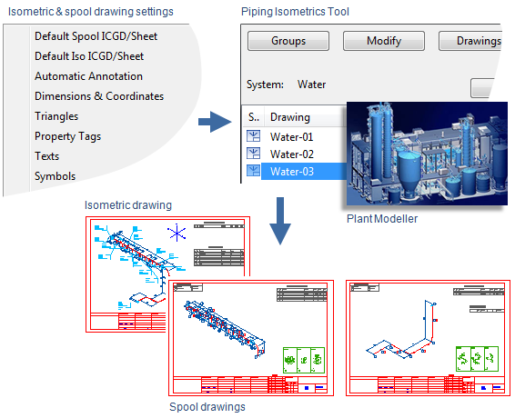
Isometric drawings and spool drawings
An isometric drawing uses isometric projection to display three-dimensional objects such as pipelines on two-dimensional drawings. In these drawings, all piping objects are presented as isometric symbols. Isometric drawings are dimensioned and labeled automatically. Also manual editing is possible, but it is not recommended.
Piping geometries can be divided into spools. A spool is a group of connected objects that will be prefabricated as a single unit. A spool drawing represents the prefabricated unit.
The image below illustrates the process of creating isometric and spool drawings in the Piping Isometrics & Spools application, based on piping geometries defined in Plant Modeller. For more details, see Piping Isometrics & Spools.
Alternatively, you can create piping isometrics directly on the Piping Isometric tab and spool drawings on the Pipe Spools tab of Plant Modeller.