Filter box
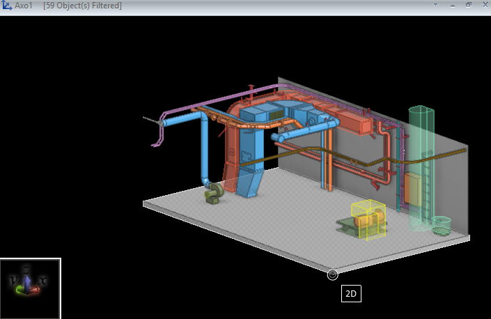
The filter box specifies which part of the model area is visible to the user in a specific work view. The filter box can be adjusted as often as needed. You can start the following commands from the 3D-digitize > Filter box context menu of the active work view or by using the related keyboard shortcut.
Make view to cover box (Alt+V)
This command sets the view limits in the View properties dialog so that they define the same area as the current filter box.
Edit box (Shift+4)
This command opens the Edit Filter Box dialog where you can define the exact size and location of the filter box.
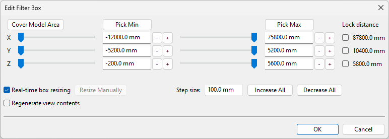
You can resize the filter box as follows:
-
Click Cover Model Area to set the filter box so that it contains the whole model area.
-
Click Pick Min/Pick Max to pick the min/max corner of the filter box from the model.
-
Click Increase All/Decrease All to move all sides of the filter box by Step size.
-
Click +/- to move the given side of the filter box by Step size.
-
Drag a min/max slider in the required direction.
-
Edit a min/max value manually. It can be millimeters, a plane name from the coordinate system, or an alias.
You can shift the filter box as follows:
-
Select the Lock distance option and click +/- to shift the filter box in the given direction by Step size.
You can set these options as appropriate:
-
Step size – Define how much the min/max values change each time you click an increase or decrease button.
-
Real-time box resizing – This is selected by default so that changes to the filter box are immediately visible in the work view. If you clear this option, you must click Resize Manually to update the work view.
-
Regenerate view contents – Select this option if changes to the filter box should immediately regenerate the work view. This will, for example, make hidden objects visible.
Get box limit from current location (Ctrl+5)
This command opens a graphical tool where you can adjust the filter box by selecting which side or corner of the filter box to move to the current cursor location.
Note: Navigate the cursor to the required location before launching this tool.
Editing the Filter Box in Axis-Oriented Views
If the view direction is along the X, Y, or Z axis, a square-shaped tool is used for adjusting the filter box.
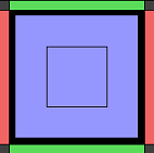
This tool has a number of hotspot areas in its outer edges and in the center. If the active work view is shaded, moving the mouse cursor to such hotspot displays a preview of the filter box that would be created. In the preview, the part of the model area that would be inside the filter box is colored.
Use the tool to adjust the filter box as follows:
- Move filter box face to the current cursor location by clicking the respective side bar of the tool.
- Move filter box edge to the current cursor location by clicking the respective corner of the tool.
- Move the furthest filter box face (in the view direction) to the current cursor location by clicking the innermost square.
- Move the closest filter box face (in the view direction) to the current cursor location by clicking the second square from the center.
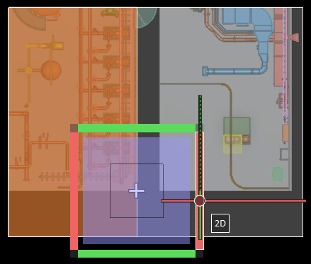
In this example, the user has navigated to the floor surface in the lower-right corner of the room on the left, in a shaded top view.
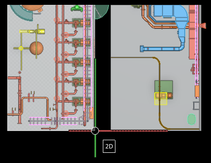
When the user opens the filter box tool, the current cursor location is shown as a white cross. The user can adjust the filter box in the following ways.
– If the user selects the side bar on the right of the tool, the respective face of the filter box is moved along the X axis to the cursor position. The Y and Z limits of the filter box remain unchanged.
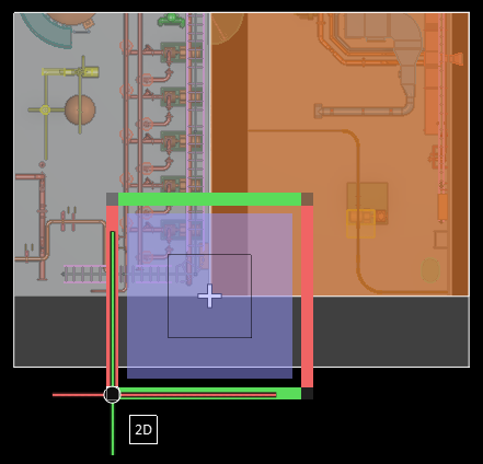
– If the user selects the lower-left corner of the tool, the adjacent faces of the filter box are moved along the X and Y axes to the cursor position. The Z limits of the filter box remain unchanged.
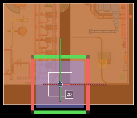
– If the user selects the innermost square of the tool, the filter box maximum in current view direction is moved along the Z axis to the cursor position. The X and Y limits of the filter box remain unchanged. Because the cursor is on the floor surface, the floor object would be outside the box and not displayed.
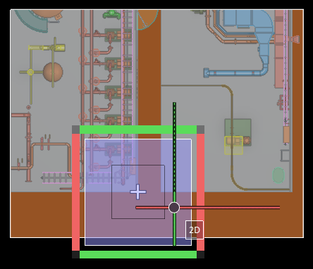
– If the user selects the second square from the center of the tool, the filter box minimum in current view direction is moved along the Z axis to the cursor position. The X and Y limits of the filter box remain unchanged. Because the cursor is on the floor surface, anything on top of the floor object would be outside the box and not displayed.
Editing the Filter Box in Axonometric Views
If the view direction is axonometric, a cube-shaped tool is used for adjusting the filter box. You can freely rotate the cube and then select from it the face or the corner of the filter box that should be moved to the current cursor position.
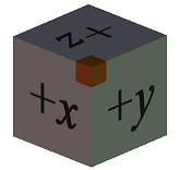
This tool has a number of hotspot areas, and if the active work view is shaded, moving the mouse cursor to a hotspot highlights the part of the model area that would be inside the filter box. Observe the color highlighting as well as the axis indicator letters of the cube and the work view to make sure that you are setting the filter box in the expected location.
In this example, the user has navigated to the corner of the floor object under a compartment and then opened the filter box editor cube. The user has rotated the cube so that moving the designated corner of the filter box to the cursor position would allow only that single compartment to be inside the filter box.
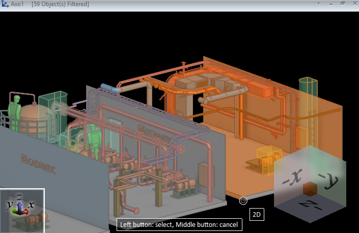
When the user clicks the cube to accept this location, all other compartments, and anything below the floor object of the included compartment, are outside the filter box and not displayed.
