Configuring penetrations
This chapter describes how to configure penetrations in CADMATIC Hull integration. These instructions are valid and the penetrations submenu is active only if you have installed CADMATIC Plant/Outfitting with Hull integration.
Configuration
Plates are considered to be Hull plates if they are of type Equipment and they have Hull specific attributes like "Hull Block number".
When you use the Penetration tool to insert piping penetrations the default value for the diameter of the hole is determined as follows:
- If the part that penetrates the plate has a dimension named PlHoleDia, then the value of that dimension is used.
- Otherwise the first diameter of the part incremented by a clearance value of 5 mm is used. The script that runs this tool uses short codes in the default specification (spec number 1) of the pipe to determine which parts are to be used in each penetration type.
For other penetration types than hole a standard component with geometry type 14 DM_GT_PENETR must be created (except inner bushing). The standard component with needed sizes must be located under the correct functional description in piping specification. The following paragraphs give necessary info of short codes and dimensions that are needed. For geometry type penetration (Geometry type nr 14 "DM_GT_PENETR") second length required by the geometry type must be 0.5 x first length.
All the examples mentioned below are available in the CADMATIC example project.
Double bushing
Double Bushing consists of two standard component outer and inner bushing. Short code ".obu" specifies the outer bushing. Geometry type must be penetration (Geometry type nr 14 "DM_GT_PENETR"). Short code ".ibu" specifies the inner bushing. This part should be defined so that only one end is compatible with pipe end. The other end must be compatible with the ends of the outer bushing. The geometry type must be part with 2 points (Geometry type nr 4 "DM_GT_2P"). Also there must exist a second length dimension that measures the overall length of the part. The first one measures the geometric length. The overall length is needed to check that there is enough straight pipe left around the penetration.
Outer Bushing ".obu" and Inner Bushing ".ibu"
Single bushing and hole reinforcement bushing
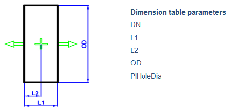
Short code ".sbu" specifies the single bushing. Geometry type for these parts must be penetration (Geometry type nr 14 "DM_GT_PENETR"). In addition to the two lengths required by the geometry type, these parts need a third length dimension which measures the overall length. This is needed to check that there is enough straight pipe around the penetration. In this check the bushing is considered to be symmetrical. Hole Reinforcement Bushing is meant for non-water tight penetrations and then the OD is normally just bigger. Short code for functional description is ".sbuhr".
Bulkhead penetration flanged in bulkhead
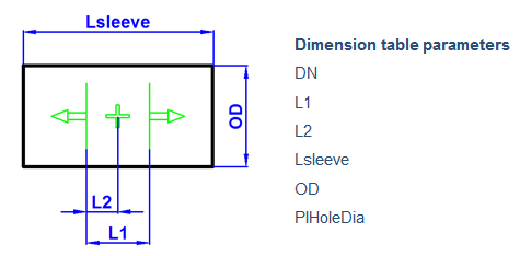
Short code ".bhpp" specifies bulkhead penetration pieces, where penetration is located into bulkhead level. Geometry type for these parts must be penetration (Geometry type nr 14 "DM_GT_PENETR").
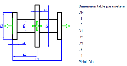
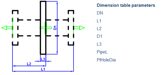
Penetration piece flanged/flanged on bulkhead with possibility to be created from pieces
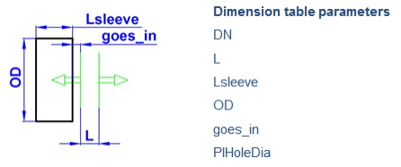
This catalog part is similar to previous except the penetration is located on bulkhead. Geometry type for these parts must be penetration (Geometry type nr 14 "DM_GT_PENETR"). Short code of functional description in specification ".bhppff".
The same penetration type can be instead created from pieces and so uses same short code ".bhppff". In this case dimension table must have a dimension named PipeL. This measures the length of the flanged pipe between gasket faces of the flanges. Default pipe and flange (from the 1st specification) are used to build the flanged pipe.
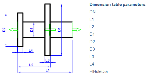
Penetration piece flanged/butt welded on bulkhead
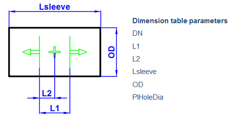
Penetration is located on bulkhead. Geometry type for these parts must be penetration (Geometry type nr 14 "DM_GT_PENETR"). Short code of functional description in specification ".bhppfw".
Penetration flange
Short code ".pflg" specifies penetration flanges. Geometry type for these parts must be penetration (Geometry type nr 14 "DM_GT_PENETR"). Short code "f" (default flange) defines the flanges (from the 1st specification) that are added to the pipe and connected to the penetration flange.