Splitting pipeline geometry into several isometrics
When isometrics are made per pipeline, the geometry of one isometric group can occasionally become very complex, and the resulting isometric drawings might be very difficult to read and interpret. To overcome this issue, complex geometries can be divided into multiple smaller geometries using automatic splitting. Creating more isometric groups will mean a higher number of drawings, but the drawings will be clearer and more useful.
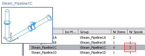
In the picture below, a steam pipeline is split into four separate isometrics 1A…1D, and Steam_Pipeline1C is divided into three spools using a flanged connection as the splitting rule. Usually, the administrator defines the rules that automatic splitting uses, and the designer is not supposed to change them.
To use automatic splitting, enable it in Documents > Piping Isometrics > Tools > Options > Configure Piping Isometrics.
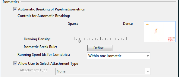
Using the Fill rate slider, define whether to create sparse or dense drawings. Slide the control to the left to have fewer parts per isometric group and more drawing. Slide the control to the right to have more parts per isometric group and fewer drawings.