3D Attachments
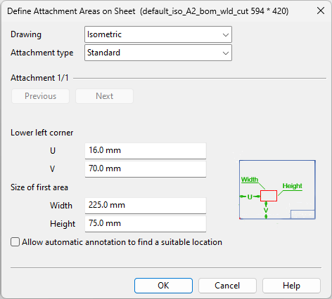
In the Define Attachment Areas on Sheet dialog, you can define the following settings. If attachments are exported from Plant Modeller, these settings define the placement and the size of the attachments in the document. You can define an area for a Standard (main) view and three different areas for multi-pipe penetration plates. Depending on document type, the settings can be applied to isometric or spool drawings or just for isometric drawings.
-
Drawing – Select Isometric or Spool.
-
Attachment type – Select Standard or Multi-pipe penetration plate.
-
Lower left corner – Define the lower-left corner of the attachment area as a measurement from the lower-left corner of the drawing sheet.
-
Size of first area – Define the width and the height of the attachment area.
-
Allow automatic annotation to find a suitable location – Select this option to allow automatic annotation to try to place attachments so that they do not collide with isometric drawings. For this to succeed, automatic annotation must be allowed to load attachments and get a suitable attachment area location, and the original attachment area must be defined inside the drawing area.
Click Next to define another attachment area.
Note: Attachments are saved to the document repository as .dwg files. Documents that have many attachments increase the size of the document repository.