Dimensions & Coordinates
In the Dimensions & Coordinates Settings dialog, you can define the following settings.
Dimension
-
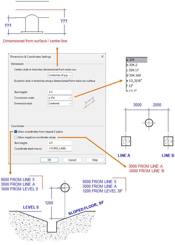
Centric stub-in branches dimensioned from main run – Select whether to dimension this type of branches from the centerline or from the surface (silhouette edge) of the main pipe.
Eccentric stub-in branches are always dimensioned from the surface of the pipe.
Note: Drawings display "(SOP)" after a branch dimension value that is measured from the surface of the pipe.
-
Text height – Specify the height of the text in dimensions (including triangle dimensions).
-
Conversion code – Select the conversion code to use for defining the precision and the unit of the dimensions. The conversion codes are described in Format strings.
-
Dimension text – Select where the dimension text should be placed in relation to the dimension line:
- Above – The dimension text is placed above the dimension line.
- Centered – The dimension text is placed over the dimension line.
If there is not enough space in the designated location, a leader line is automatically inserted and the dimension text is moved to the end of the leader line.
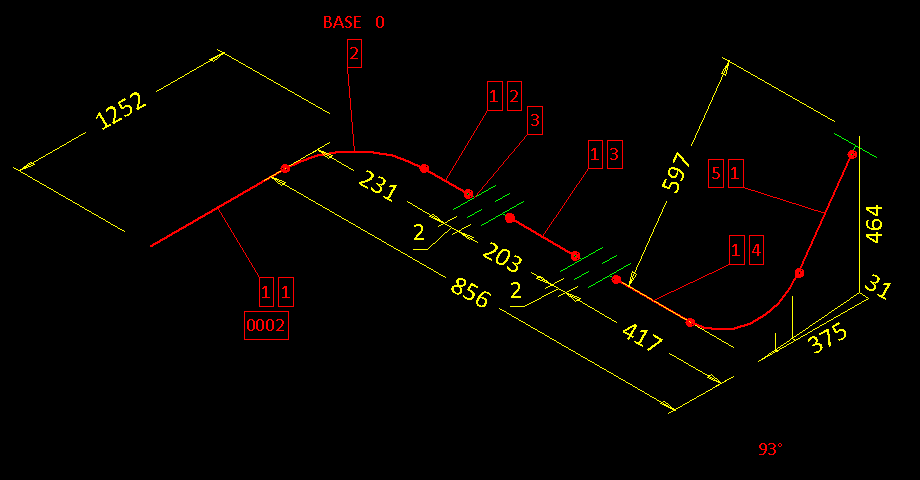
 Show/hide example
This example shows dimension texts centered to the dimension lines. In some cases, a leader line has been inserted.
Coordinate
-
Allow coordinates from sloped Z-plane – Select this setting if you have defined a coordinate system with a slanted Z-plane and want to allow coordinates to use it as a reference plane.
-
Allow negative coordinate values – Select this setting if coordinates should use the nearest plane (up or down) as a reference plane. If cleared, coordinates use a plane that provides positive values.
-
Text height – Specify the height of the text in coordinate values.
-
Coordinate label macro – Coordinate texts are generated by a script which is editable. The default coordinate label macro is "COORD_LABEL". If you want to use some other macro stored in the project script library, enter its name in this field.
-
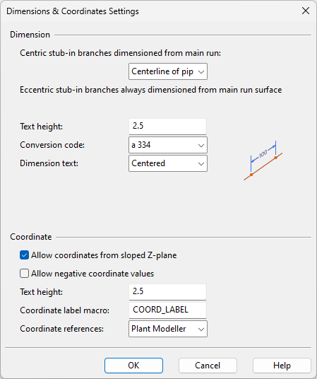
Coordinate references – Select which coordinate references configuration to use for isometric drawings created on the Piping isometric tab or for pipe spool drawings created on the Pipe spools tab of Plant Modeller.
-
Plant Modeller – Select this to use File > Environment > All library and project > [project] > Configuration > Plant Modeller > Coordinate references.
-
Isometric – Select this to use File > Environment > All library and project > [project] > Configuration > Isometric Drawings > Coordinate references.
-