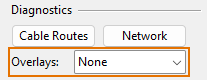
Overlays
The Overlays setting allows the cable router to add a red marker to places that require the user's attention. These special markers can be seen in Plant Modeller work views and in views opened by the cable routing tools; they are removed from work views when you switch from the Cabling tab to some other tab.
The overlay options are:
-
None – Overlays are turned off.
-
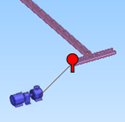
Open ends – Shows a red pin next to a node at the end of a cable tray if the cable route cannot continue anywhere from there.
This might mean, for example, that something is blocking the route or that nodes are missing and the nodal network should be recreated.
 Show/hide example
In this example, the cable jumps from the head equipment to the first node but cannot go further.
-
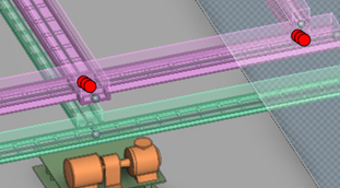
Combined nodes – Shows a red multi-circle icon next to a combined node.
The cable router adds a combined node to locations where two or more segments intersect, overlap, or end. Using the combined node instead of several individual nodes makes it easier for the tool to search for possible cable routes. When creating node IDs, other nodes are given an ID based on the data query defined in the cable router settings (see Network), and the combined node gets its ID from the first node that the program finds from this location.
Often this overlay type simply allows the user to get a better understanding of the cable routes, but in some cases it might also indicate the need to modify the 3D model. For example, if segments overlap because cable trays are partially duplicates, the model should probably be adjusted.
Show/hide example
In this example, two combined nodes indicate locations where the cables are routed via the same point.
-
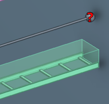
Orphan nodes – Shows a red question mark next to a node that is no longer in the same location as the cable way host object that was used to generate the node.
Usually this means that the host object has been moved or deleted, and the problem can be solved by recreating the nodal network.
Show/hide example
In this example, the cable tray has been moved downward but the node is still where the cable tray used to be.
-
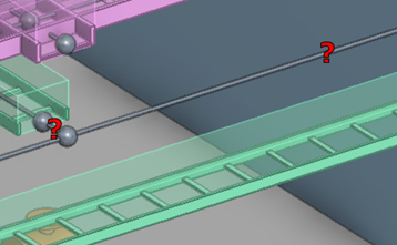
Orphan segments – Shows a red question mark next to a segment that is no longer in the same location as the cable way host object that was used to generate the segment.
Usually this means that the host object has been moved or deleted, and the problem can be solved by recreating the nodal network.
Show/hide example
In this example, the cable tray has been moved downward but the segments are still where the cable tray used to be.
-
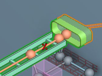
Overfull segments – Shows a red percentage icon over a segment that has been overfilled.
Show/hide example
In this example, the cable material has been changed to a thicker one, causing the segment to be overfilled.
-
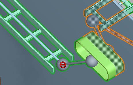
Disabled objects – Shows a red "no entry" icon over a network object that has been disabled.
Show/hide example
In this example, one node has been disabled.