3D-import options
In the 3D-Import Options for '<file name>' dialog you define the import options for a data file to be imported to Plant Modeller. 3DD files can use shared settings stored in the COS server, but for other formats you must define the settings per data file. You can, however, use Copy/Paste in the 3D-Import Manager dialog to copy settings from one import to another.
When opening the options, if prescanning has not been performed yet you are prompted whether to allow attributes and object extents to be scanned from the selected import files. Prescanned attributes allow you to map objects to systems based on attributes, and to map imported attributes to Plant Modeller attributes; prescanned object extents allow you to see the bounding box of the objects in the model area before the import. If these are not relevant for you, you can skip the prescanning.
The import options are defined on three tabs, and you can select whether to save options locally or to COS.
General tab
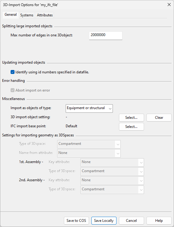
On the General tab, you can specify general import settings.
Splitting large imported objects
-
Max number of edges in one 3Dobject – Specifies the maximum number of edges to include in a single object. The default value is 20,000,000. If the number of edges in an incoming object exceeds this threshold value, the importer splits the object into multiple objects.
-
Detect smooth surfaces – Select this option to allow 3DP and JT file imports to scan polygon data for smooth surfaces. Max angle between smooth faces specifies the maximum angle between smooth surfaces.
-
Linear deflection – In 3DDX import, specifies the maximum distance between a line and a curve that the line approximates.
-
Angular deflection – In 3DDX import, specifies the maximum angle between two consecutive polyline segments.
-
Deviation – Specifies how object geometry is generated in DWG import. This setting defines the maximum approximation distance to use for controlling the tessellation of solids. A small value creates more triangles and therefore produces smoother, more detailed 3D objects—a large value creates fewer triangles and therefore produces rougher 3D objects. The value can be negative or positive, the default is 32.
-
JT Geometry – Specifies how object geometry is generated in JT import. This can be set to one of the LOD levels in the JT file, or you can choose to tessellate the XT brep geometry present in the JT file.
Updating imported objects
-
Identify using id numbers specified in datafile – Select this option to allow the import to use the object IDs in the data file to identify which previously imported objects have changed and can be updated. Do not change this setting after the import.
Error handling
-
Abort import on error – Select this option to allow problematic object geometry to stop the import process.
-
Maximum wait time before abort [min] – In 3DDX import, specifies the number of minutes to wait before determining that import is to be aborted.
Miscellaneous
-
Import as objects of type – Select how to import objects.
- Equipment or structural – Objects with connection nodes are imported as equipment, others are imported as structural objects.
- Equipment – All objects are imported as equipment. If imported object has no nodes, one node is automatically added to the origin.
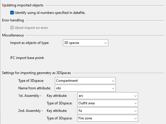
- 3D spaces – All objects are imported as 3D spaces. The option is only available if there are valid 3D space types. If selected, also define the additional 3D space settings.
-
3D import object setting – You can use a 3D import object mappings configuration to convert IFC beams and plates to CADMATIC objects. Click Select to select the configuration to use, or click Clear to clear the current setting.
-
IFC import base point – You can define the offset between the coordinate systems of the 3D model and the IFC file by specifying their origin points. After import, the offset is shown in the X offset, Y offset, Z offset columns of the import manager.
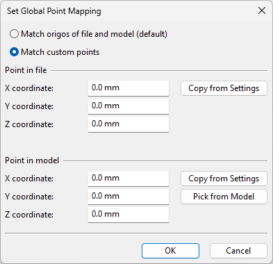
Select – Opens the Set Global Point Mapping dialog.
 Show/hide details
-
Match origos of file and model (default) – Select this option to set the origin point of the IFC model to the origin point of the 3D model (design area).
-
Match custom points – Select this option to offset the IFC model in the design area. If all the values are 0, then the default origin points are used.
-
Point in file – Specify a custom reference point for the IFC file. You can click Copy from Settings to copy the values from another IFC export configuration, if available.
-
Point in model – Specify a custom reference point for the 3D model. You can click Copy from Settings to copy the values from another IFC export configuration, if available, or you can click Pick from Model to pick the point from the model area.
-
-
-
Include hidden objects – Select this option to include objects defined as hidden in the import.
-
Include texts – Select this option to include texts in the import.
-
Include wireframes – Select this option to include wireframe geometry in the import.
-
Collapse group attributes to objects – Select this option to import parent group attributes as object attributes, so that hierarchy levels are defined at the object level. When not selected, parent group attributes are retained in the imported groups.
-
NWD point mapping – You can define the offset between the coordinate systems of the 3D model and the NWD file by specifying their origin points. After import, the offset is shown in the X offset, Y offset, Z offset columns of the import manager.
Select – Opens the Set Global Point Mapping dialog.
Show/hide details
-
Match origos of file and model (default) – Select this option to set the origin point of the IFC model to the origin point of the 3D model (design area).
-
Match custom points – Select this option to offset the IFC model in the design area. If all the values are 0, then the default origin points are used.
-
Point in file – Specify a custom reference point for the IFC file. You can click Copy from Settings to copy the values from another IFC export configuration, if available.
-
Point in model – Specify a custom reference point for the 3D model. You can click Copy from Settings to copy the values from another IFC export configuration, if available, or you can click Pick from Model to pick the point from the model area.
-
-
-
Import step hierarchy – Select this option to include the STEP file object hierarchy in the import. The imported objects are separate Plant Modeller model objects that are members of the import group. The object properties include a link to the original import file; detaching the file in the import manager will remove this link. Any subsequent re-imports will replace the previously imported object. When not selected, the object hierarchy is not included, and the object can be updated by re-importing.
Settings for importing geometry as 3Dspaces
When the Import as objects of type option is set to '3D spaces', you can specify the following settings.
-
Type of 3Dspace – Select the 3D space type for the imported objects from the drop-down list. The list includes the 3D space types configured in Containment setup, including all sublevel hierarchies.
Note: The type cannot be changed after the data file has been imported once.
Note: Sub-blocks are imported as 'orphan spaces'. They must be assigned to the appropriate hierarchy level in the containment browser. See Logistics hierarchy.
-
Name from attribute – Select the attribute that will be used to name the imported 3D space objects. The names derived from the chosen attribute will be displayed, for example, in the containment browser and the Properties pane.
The imported 3D spaces can also be set to form assemblies. A single import configuration can generate two types of assemblies. For example, if the geometries are imported as Compartments, they can be assembled into Outfit Areas and Fire Zones. These combined assemblies will be generated when imported 3D spaces share the same value in the Key attribute defined in the following settings.
-
1st. Assembly
-
Key attribute – Select the attribute that will be used to merge 3D spaces into an assembly. If you do not wish to create assemblies, leave this set to 'None'.
-
Type of 3Dspace – Select the 3D space type for the first set of assemblies.
-
-
2nd. Assembly
-
Key attribute – Select the attribute that will be used to merge 3D spaces into an assembly. If you do not wish to create assemblies, leave this set to 'None'.
-
Type of 3Dspace – Select the 3D space type for the second set of assemblies.
-
In this example, geometries are imported as 3D spaces of type 'Compartment', and the name of the compartment is taken from the GUID (obi) of the model object. The file being imported contains the attributes 'Area code' (arc) and 'Fire zone' (fiz), and the import is configured to create assemblies according to these attributes.
Systems tab
On the Systems tab, you can specify how to assign the imported objects to systems.

Systems for imported objects
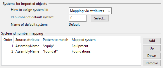
How to assign system id – Select the method to use for assigning systems to imported objects.
- Use default system – All imported objects use the same, default system.
- Keep imported value – Imported objects use the system defined in the sid tag of the import file.
- Specify mapping – Imported objects are mapped to systems based on system IDs, as defined in the System id number mapping table.
- Mapping via attributes – Imported objects are mapped to systems based on attributes, as defined in the System id number mapping table.
- Mapping via attribute values – Imported objects are mapped to systems based on attribute values, as defined in the System id number mapping table.
Id number of default system – Specify the default system ID to use. Click Select to select it from the project.
System id number mapping
The System id number mapping table is used by some of the mapping options that you select as described in Systems for imported objects. After selecting the appropriate mapping option, you see the applicable mappings and can edit them as needed.
- Click Add to create a new mapping.
- Select a mapping and use the Up and Down buttons to specify the order in which the mappings are evaluated during import.
- Click Remove to delete the currently selected mapping.
If using 'Specify mapping'
If How to assign system id is set to 'Specify mapping', you can use the mapping table to map multiple imported system IDs to a single target system. As a result, imported objects use the mapped system instead of the system specified in the import file.
In the example below, imported system IDs from 1 to 10 are mapped to the Water system, and IDs from 200 to 215 are mapped to the PULP system.

If using 'Mapping via attributes'
If How to assign system id is set to 'Mapping via attributes', you can use the mapping table to map attribute values that match a user-defined pattern to specific systems. As a result, objects that have a specific attribute value use the mapped system instead of the system specified in the import file.
In the example below, if the value of the AssemblyName attribute contains the string "equip", the object uses the Equipment system, and if the value contains the string "foundat", the object uses the Foundations system.
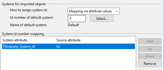
If using 'Mapping via attribute values'
If How to assign system id is set to 'Mapping via attribute values', you can use the mapping table to map imported attributes to system attributes that have the same attribute value. This allows objects to be imported to several systems without having to specify the actual system IDs during the import.
When adding the mapping rule and you have prescanned the import file, you are prompted to select the source attribute from a list; without prescanning you must specify the attribute name manually. Then you are prompted to select the target COS object attribute (only string-type attributes are listed).
In the example below, if the value of the imported attribute tsi is for example "CC_Water", and the project contains a system whose attribute Thirdparty_System_Id has the same value, the object is assigned to that system.
Attributes tab
On the Attributes tab, you can map imported attributes to existing Plant Modeller attributes, so that the imported objects will have relevant Plant Modeller attributes. The way the mapping is performed depends on whether prescanning has been run on the current data file.
- If prescanning has not been performed, there are Add and Remove buttons on the right side of the Attribute mapping pane. When adding a mapping, you are prompted for the name of the attribute in the data file, and then you can select the target Plant Modeller attribute from a list.
- If prescanning has been performed, the Modify button on the right side of the Attribute mapping pane opens a dialog where you can perform mapping as described below.

To define mappings using prescanned attribute data, click Modify. The Attribute Mapping dialog opens. The Source attributes pane lists the attributes found in the data file and sample values obtained from prescan (if performed), and the Target attributes pane lists Plant Modeller attributes. You can use the filter fields to list only attributes that match the filter string.
- To map incoming attributes to Plant Modeller attributes, select one or more attributes from the source attribute list, then select the target attribute to map them to, and click Map.
- If there are incoming attributes that can be ignored in import, select them from the source attribute list and click Ignore. This moves them to the Ignored pane.
The Mapped pane displays the current mappings. If a previously created mapping refers to an attribute that is no longer available, the mapping has a gray background; you can choose whether to keep such mappings for future use or unmap them.
The Ignored pane displays the source attributes that you have chosen to ignore. You can put them back to the source attribute list, if needed, by selecting the items and clicking Return.

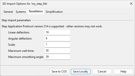
Tessellation tab
On the Tessellation tab, you can specify settings for tessellating geometries imported from STEP (.stp) files and other files that can be imported via intermediate conversion to the STEP application protocol 214 (AP214) format.
-
Linear deflection — Specifies the maximum distance between an imported higher-order surface (such as spline surface, which are typical for Mechanical CAD models) and its triangulated approximation, using a value from 0.1 to 100.
-
Angular deflection — Specifies the maximum angle between neighboring (approximated) triangles, using a value from 0.1 to 6.283185.
-
Scale — Specifies the scaling factor for scaling the generated triangle mesh up or down.
-
Maximum wait time — Specifies how long the program will wait for the import to finish before determining that it has failed (1–60 minutes).
-
Maximum smoothing angle — Specifies edge visibility, using a value from 0 to 90. Increasing the value makes the imported model look smoother, but too high value might cause necessary edges not to be shown.
Note: Smaller deflection values result in more triangles being created, which can degrade performance in complex models. Eventual runtime performance depends on the total number of complex models that are imported into the model area, and to optimize performance you should import objects as coarse as is acceptable to you. For more information on linear deflection and angular deflection, see the Open Cascade Technology documentation at https://www.opencascade.com/doc/occt-7.1.0/overview/html/occt_user_guides__modeling_algos.html#occt_modalg_11_2.
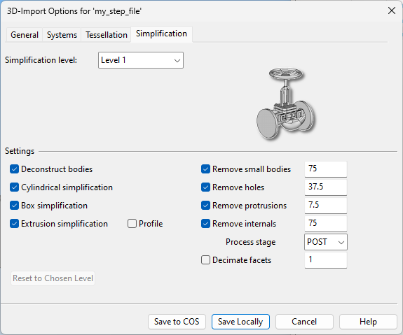
Simplification tab
On the Simplification tab, you can specify settings for simplifying geometries imported from STEP (.stp) files and other files that can be imported via intermediate conversion to the STEP application protocol 214 (AP214) format. Simplification aims at reducing the size of the imported 3D objects without losing important visual information.
Note: To use these tools, your environment must have the separately installed CADMATIC Simplifier tool and a separate license.
-
Simplification level – To simplify models, select the desired simplification level from the drop-down list, and then adjust the individual settings as required.
Show/hide examples
Default, no simplification
Level 1, least simplification
Level 2, moderate simplification
Level 3, most simplification
-
Deconstruct bodies – Select this option to identify natural split points, such as sharp changes in the model profile.
Turning this off can decrease the processing time, but the models will be less simplified.
-
Cylindrical simplification – Select this option to replace approximately cylindrical bodies with a cylinder.
Turning this off can slightly decrease the processing time.
-
Box simplification – Select this option to replace approximately box-shaped bodies with a box.
Turning this off can increase the processing time and the workload of the other tools.
-
Extrusion simplification – Select this option to remove holes and details from extruding forms.
Profile – Select this option to remove holes from extruding faces.
-
Remove small bodies – Select this option to remove bodies whose bounding box is smaller than the threshold value.
-
Remove holes – Select this option to remove holes whose entry/exit size is less than the threshold value, regardless of cross section or form.
-
Remove protrusions – Select this option to remove protruding forms whose start/end size is less than the threshold value, regardless of cross section or form.
-
Remove internals – Select this option to remove internal details as well as openings that are smaller than the threshold value.
This can increase the processing time, but it may also simplify the model more.
Process stage – Select at what stage of the simplification process to remove the internals: at the beginning (PRE), at the end (POST) or at both times (BOTH).
- Decimate facets – Select this option to reduce the facet count by the tolerance value. The higher the value the less accurate the model becomes.
Saving the import options
In the 3D-Import Options for '<import name>' dialog, you can select whether to save the options locally (per import file) or to COS so that multiple imports can share the same settings.
If you already have multiple imports of a given file type that use the same settings but the settings are stored locally (defined separately for each import file), you can make them more manageable by moving the settings to COS. To do this, first use Save to COS to save one instance of the settings to COS, and then use the Assign function in 3D-Import Manager to assign the settings to all applicable imports.
-
Save to COS — Save the options to the COS server with a user-specified name. Then you can assign the settings to any import file that uses the same file format.
Note: If you edit existing options stored in COS, the changes will affect all imports that are assigned to use those settings.
-
Save Locally — Save the options locally in a file. The settings will be applied to a single import file.

-
Save As – In the Project Environment dialog, in [project] > 3D Import Settings > 3D Import Settings, you can select to create new import configuration objects or edit existing ones if Project Environment was opened from Plant Modeller (not from CADMATIC desktop). In this case the dialog displays a Save As button that allows you to save the settings in COS with a different name.

