Commands for defining direction
-
Direction from basepoint to cursor (Space) – Causes the system to compute the direction vector from the start point to the digitized point. If the distance between these points is too small the system displays an error message in the message pane and re-starts 3D-digitizing. Otherwise the resulting components are filtered so that the component is set to zero if its absolute value is less than a given tolerance value.
-
Set X, Y, and Z coordinates (C). The legal values for dX, dY, and dZ are [-1, 1]. An empty field means the value 0. This is used mainly for axial directions.
-
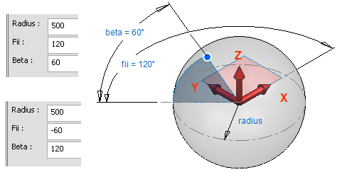
Set spherical coordinates (S). You define two directions, fii and beta. Fii is measured from the positive portion of X axis counter-clockwise. Beta angle is measured from the XY plane. Default values are computed from the vector between the previous active point and current location.
-
Release cursor (Shift+A) – Releases the cursor to move freely.
-
Back to basepoint (Home) – Resets the vector that the user has defined.
-
Direction from main axis >
-
X axis (Alt+X) – Takes the positive direction of the X axis {1, 0, 0}.
-
Y axis (Alt+Y) – Takes the positive direction of the Y axis {0, 1, 0}.
-
Z axis (Alt+Z) – Takes the positive direction of the Z axis {0, 0, 1}.
- -X axis (Alt+Ctrl+X) – Takes the negative direction of the X axis {-1, 0, 0}.
-
-Y axis (Alt+Ctrl+Y) – Takes the negative direction of the Y axis {0,-1, 0}.
-
-Z axis (Alt+Ctrl+Z) – Takes the negative direction of the Z axis {0, 0,-1}.
-
-
Direction from connection (Shift+Q) – Takes the direction from the connection point or end normal of the beam nearest to the digitized point. This command checks only points that belong to objects close enough to the digitized point. After picking the connection point you verify whether the direction is to point out of the connection face (the first alternative) or in the opposite direction. A short line is drawn in each active view from the starting point to the default direction corresponding to a Yes answer.
-
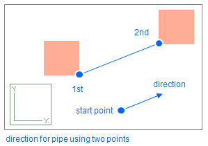
Direction from point1 to point2 (Shift+V) – Defines a vector from point P1 to point P2. A small cross drawn in each active view shows the location of P1 when P2 is defined. When P2 is successfully defined the system computes the direction vector from P1 to P2. If the distance between these points is less than 0.1, the system displays an error message in the message pane and returns to define P2. To set the direction of pipe according to two points (see the picture below), do the following:
- Start routing a pipe and click the start point.
- Restore the cursor to original location (Shift+R).
- Lock cursor using 5 and 6 (not mandatory).
- Press A (Lock to Line) to define the direction.
- Select Point1 -> Point2 or press Shift+V.
- Click the points and unlock cursor (if locked) by pressing 5 and 6.
-
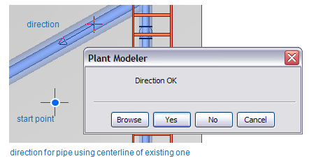
Direction from nearest centerline (F11 or Shift+C) – Takes the direction of the centerline of the pipe, air duct, or beam nearest to the digitized point. When the centerline is identified you verify which direction along the centerline (the first alternative) or in the opposite direction. A short line is drawn in each active view from the starting point to the default direction corresponding to a Yes answer. To set the direction of pipe according to centerline of existing pipe (see the picture below) do the next steps:
-
Start routing a pipe and click the start point.
-
Restore the cursor to original location pressing Shift+R.
-
Lock cursor using 5 and 6 (not mandatory).
-
Press A (Lock to Line) to define the direction.
-
Move cursor near the existing pipe and press Shift+C.
-
To accept the direction click Yes or to change the direction click No.
-
-
Direction from nearest edge (Shift+E) – Takes the direction of the edge nearest to the digitized point. This command checks equipment, structural components, beams, ducting components, and cable tray components that are close enough to the digitized point. When the edge is identified you verify the direction. A short line is drawn in each active view from the starting point to the default direction corresponding to a Yes answer.
-
Direction from nearest 2D line (Shift+D) – Takes the direction of the 2D line nearest to the digitized point in the control view. The depth coordinate of the direction vector in the view coordinates will be 0.0. When the 2D line is identified, the user is prompted to verify the direction. This command is applicable only if 2D annotations have been activated for the control view.
-
Perpendicular to 2 other directions – Takes the direction of a vector that is perpendicular to a plane defined by two points that the user selects from the model.
-
Normal from nearest face (F) – Takes the normal pointing out of the planar face that is nearest to the digitized point. This command checks only equipment, structural components, beams, and Ducting components that are close enough to the digitized point.
-
Normal from nearest surface (Shift+S) – Takes the normal pointing out of the surface that is nearest to the digitized point.
-
Normal from plane through 3 points (V) – Takes the normal of a plane defined by three points. When the plane is defined you can verify whether the direction is to point in the default direction or in the opposite direction. A short line is drawn in each active view from the starting point in the default direction corresponding to a Yes answer.
-
Normal from nearest virtual plane (Shift+F) – Takes a normal to the plane generated from a 2D line in the control view by sweeping it in the view direction. The system searches for the line that is nearest to the location returned from 3D-digitizing. When the plane is generated you verify whether the direction is to point out of the plane (the first alternative) or in the opposite direction. A short line is drawn in each active view from the starting point to the default direction corresponding to a Yes answer.
-
Cancel (Esc) – No direction vector is defined.
Direction definitions (table of commands)