Add components
Use the Add component context-menu command to insert a piping component such as an elbow, reducer, or flange to the model.
Note: You cannot use this command to insert standard components such as flow meters or supports—for more information, see Standard component.
Do the following:
-
Move the cursor to the location where you want to insert the component.
-
If you want to insert a piping component as the first part of a new pipe, pick the start point from the model, right-click and select Add component from the context menu, and define the routing direction.
-
If you are already routing a pipe and want to add a piping component to the current location, right-click and select Add component from the context menu.
The Select Component dialog opens.
-
-
Define the settings described in Select Component and click OK.
-
If the inserted component is an elbow, you are prompted to define the pipe direction after the curve. See Direction definitions.
Select Component
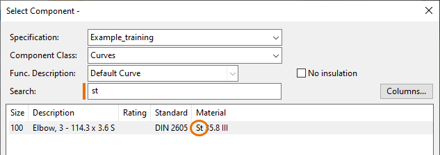
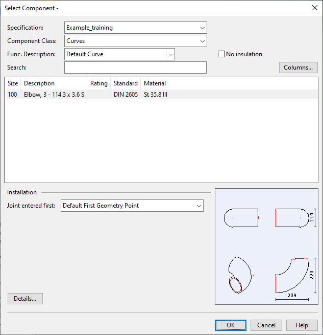
In the Select Component dialog, select the component that you want to insert to the model and specify how to connect it to the previous piping part.
-
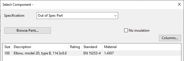
Specification – Select which specification to use (if the pipeline supports several specifications) or "Out of Spec Part", as applicable.
-
Select the Catalog Part and Part Size to use:
-
If you chose a specification, select the Component Class and Func. Description, and then select the correct size from the component list. If inserting the component to a connection point, the list only shows the compatible sizes. If the list is long, you can enter a search string in the Search field to filter the list based on the visible columns.
-
If you chose to use an out-of-spec part, click Browse Parts and select the component from the Out-of-Spec Catalog Part object browser. The selected component is shown in the component list.
-
-
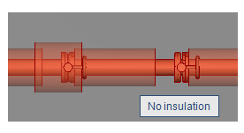
No insulation – If inserting a Standard Component and the pipeline uses insulation, you can select this option to insert the component without insulation.
 Show/hide example
In this example, one instance of a manual valve is inserted with insulation and another one without insulation.
-
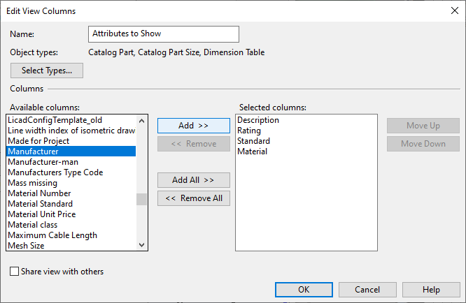
Columns – Allows selecting which columns (attributes) to show in the component list.
-
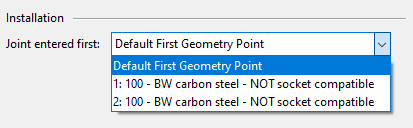
Joint entered first – If you are connecting a component to another piping part, you can select which point in the component to use for the connection. The nominal sizes must be the same and the connection faces have to be connectable according to the compatibility table described in Compatibilities between connection faces.
-
Add method – If you are connecting a component to a straight pipe, select how to add the component to it:
-
Add to end of run – The component starts from where the straight pipe ends.
-
Shorten run – The straight pipe is shortened by the length of the component (for a curve it is the side length) so that the component ends at where the straight pipe used to end.
-
-
Details – Opens an object browser for viewing more information on the selected component.