End plates

On the Structural tab, you can use the End plates > Insert tool to insert end plates onto beams and straight pipes.
Optionally, the tool can do the following:
-
Align the plate with the face of a nearby object, such as a wall or floor.
-
Make the plate bigger or smaller than the cross-section of the beam or pipe.
-
Shorten the beam or pipe by the thickness of the plate.
If the target object belongs to a Structural Unit group, the end plate is also added to that group.
If the target object is a pipe, the end plate is modeled as a standard part that does not belong to the pipeline, and therefore, is not bound to the piping specification.
Collision detection does not report contact violations or collisions between the end plate and the associated objects. Moving the plate will break the associations, allowing contacts or collisions to be reported.
Inserting end plates
You can insert end plates onto beams and straight pipes. For the plate part, you can either use a component model or create an embedded component model from suitable plate material.
Prerequisites
-
To use a standard component for the plate part, the catalog part must have the attributes 'Component type = Plate' and 'Plate type = Formed plate', and the related GDL object should define one parametric plate primitive. The insertion tool extracts boundary and thickness information from the plate primitive to determine the smallest plate size that can cover the end of the target object.

Note: We recommend using an existing component from the CADMATIC example project as a basis for creating your own end plate parts.
-
To shorten/trim the target object, the target object must be checked out to your area.
Do the following:
-
Select the Structural tab > End plate group > Insert. The End Plate Tool Settings dialog opens.
-
Specify the required settings, and click OK. The cursor's tooltip displays "Select target for end plate" and the context menu lists the commands specific to this tool.
-
To insert a plate at the end of a beam or pipe, position the cursor near the end of the target part, select Add end plate (Space) or click the part, and then press Enter. The plate is aligned with the target part and shortens the target part if you specified so in the settings.
-
To insert a plate so that it trims the end of the beam or pipe to match the non-perpendicularly aligned face of a structural object located within the auto-trimmer's maximum distance, position the cursor near the end of the target part, select Auto trim & add end plate (K), and then press Enter.
-
To insert a plate with different settings, select Tool settings (P) and change the settings as required.
-
To undo insertions, one at a time, select Undo (U).
Note: While there is no 'Redo' command within this tool, after exiting the tool you can undo/redo insertions, one at a time, by clicking Undo/Redo in the quick access toolbar.
-
To stop inserting end plates, select Done (Enter) or press Esc.


End Plate Tool Settings
In the End Plate Tool Settings dialog, you can specify the following settings.
-
Plate type – Select the type of plate to use:
-
Standard component – Select this option and click Select to choose the plate component using a Catalog Part linked to a GDL model. The insertion tool will automatically select the smallest Catalog Part Size applicable to the target object.
-
Plate – Select this option and click Select to choose the plate material. The plate will be using an embedded GDL model created by the insertion tool, which you will be able to modify with the Plate tools.
-
-
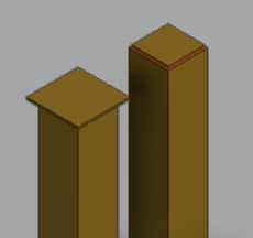
Offset – Specify an offset to make the end plate either larger (positive offset) or smaller (negative offset) than the cross-section of the target object, measured at the point where the target object is trimmed. For example, you can enter a negative offset to make space for welding an end plate inside the boundaries of a hollow steel profile.
 Show/hide image
This example shows the same end plate inserted with a positive offset (left) and negative offset (right, with welding added).
-
Shorten target by plate thickness – Select this option to shorten the target object by the thickness of the end plate. This requires that the target object is checked out to your area.
-
Add plate to same system as target – Select this option if you want the end plate to be assigned to the same system as the target object. Otherwise, select the system of the end plate by clicking
 .
. -
Max distance of auto trim target object – Specify the maximum search distance from the beam or pipe end to the potential auto-trimmer object.