Wizards for weld creation
CADMATIC offers a number of wizards that simplify creating welds. These can be categorized into two different classes: automatic and semi-automatic. When using the former you only pick the part that needs to be welded. The target for the weld is searched automatically. In the latter case you need to pick both parts that are to be welded.
Weld beam at one of its ends
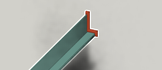
This wizard finds use in cases where end of beam is in contact to one target part at a planar face.
You are requested to pick a beam and system will find the target part to which the beam is in contact to at the end that is closest to the point where you picked the beam.
Since the search of target part is automatic this wizard does not weld beam to a target part that is in the same structural unit as the beam itself. If there is a need to create this kind of weld then use wizard that welds parts in contact (you need to pick both parts).
Weld will not be created if neither the beam nor target part belongs to the logistics 3D space of the active weld group. Also weld will not be created if there already is a weld between these parts.
After weld is created data extractor (configured in weld settings) is executed to dig out interesting information of welded parts. This information is embedded to the weld at this stage. If information of parts is changed after this then embedded information will be different.
Weld is assigned to the currently active weld group. If weld list currently shows welds in active group then information about this new weld appears in the list too.
Please note the following restrictions when using this wizard:
-
does not weld beams in contact along some side face
-
if there are more than one target face at the beam end then weld is created only with the one that is hit by ray shot through local origin of the profile. If the beam end is in contact to more than one target then you need to use wizard that allows you to pick also the target part.
How the path is computed?
To understand the restrictions you may be interested in how it computes the weld path.
Weld path is obtained from trace line that in turn is gotten by cutting the beam end by a face retrieved from the target part closest to the beam end. In an ideal case this trace line follows the complete perimeter of the beam profile along the plane. However, if the beam end is sniped or mitered then trace line naturally follows only the part that lies on then target face. Trace line is trimmed by boundary and holes on the target face. There is a weld setting that specifies the maximum offset of weld path from the target face. If this offset is exceeded then a gap is inserted to weld path to cover that part of the path that is too far from the target face.
Weld plate at its front or back face
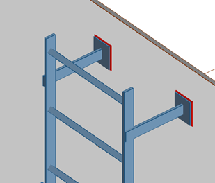
This wizard finds use in cases when you have a plate like part in contact at its front or back face to another part. A plate like part can be modeled as a piece of equipment, a structural part or a standard part.
You are requested to pick a plate and system will find the target part to which the plate is in contact to at its front or back face. If the part contains more than one geometric primitive then you need to pick that part so that cursor hits the plate primitive that you want to weld.
Since the search of target part is automatic this wizard does not weld plate to a target part that is in the same structural unit as the plate part itself. If there is a need to create this kind of weld then use wizard that welds parts in contact (you need to pick both parts).
Weld will not be created if neither the beam nor target part belongs to the logistics 3D space of the active weld group. Also weld will not be created if there already is a weld between these parts.
After weld is created data extractor (configured in weld settings) is executed to dig out interesting information of welded parts. This information is embedded to the weld at this stage. If information of parts is changed after this then embedded information will be different.
Weld is assigned to the currently active weld group. If weld list currently shows welds in active group then information about this new weld appears in the list too.
Please note the following restrictions when using this wizard:
-
If there are more than one target face in contact to the plate then weld is created only with one of them. In this case it may be more advisable to create the welds using wizard that allows you to pick also the target part.
-
This wizard does not weld plates connected at some side face. Use wizard that welds parts in contact (you need to pick both parts).
How the path is computed?
To understand the restrictions you may be interested in how it computes the weld path.
Weld path is obtained from boundary curve of the plate part. In an ideal case this trace line follows the complete perimeter of the plate along the plane. Weld path is trimmed by boundary and holes on the target face. There is a weld setting that specifies the maximum offset of weld path from the target face. If this offset is exceeded then a gap is inserted to weld path to cover that part of the path that is too far from the target face. This would happen if the plate is slightly misaligned to the target face.
Weld touching parts
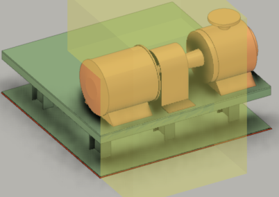
This wizard finds use in cases when you have two parts that touch at a planar face.
First you are requested to pick the part that will be welded. This should not be a hull part. Next you are requested to pick the target object to which the first part is to be welded. You need to pick this latter part so that the cursor hits the plane at which the parts are expected to touch.
Weld will not be created if neither part belongs to the logistics 3D space of the active weld group. Also weld will not be created if there already is a weld between these parts.
Weld path is obtained by cutting the first object by a face that you picked. Weld path is trimmed by boundary and holes on the target face. There is a weld setting that specifies the maximum offset of weld path from the target face. If this offset is exceeded then a gap is inserted to weld path to cover that part of the path that is too far from the target face. This would happen if the plate is slightly misaligned to the target face.
After weld is created data extractor (configured in weld settings) is executed to dig out interesting information of welded parts. This information is embedded to the weld at this stage. If information of parts is changed after this then embedded information will be different.
Weld is assigned to the currently active weld group. If weld list currently shows welds in active group then information about this new weld appears in the list too.
Weld penetrating part
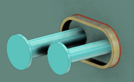
This wizard finds use in cases when you have a part that penetrates target object at planar face.
First you are requested to pick the penetrating part that will be welded. This should not be a hull part. Next you are requested to pick the target object to which the first part is to be welded. You need to pick this latter part so that the cursor hits the plane through which the other part penetrates.
If the target part is a plate and you need welds at both sides then you need two welds. For one of the welds pick the plate at its “front” face and for the other weld you need to pick it as seen from the opposite direction.
Weld will not be created if neither part belongs to the logistics 3D space of the active weld group.
Weld path is obtained either by obtaining the boundary curve of the penetration part or by cutting the part by a face that you picked. Boundary curve is preferred since created weld path will maintain arcs. If path is obtained via cutting the penetration part (can’t obtain boundary curve of axis of penetration part is not perpendicular to face at target) then arcs in the boundary curve are modeled as polylines. Weld path is trimmed by of the target face.
After weld is created data extractor (configured in weld settings) is executed to dig out interesting information of welded parts. This information is embedded to the weld at this stage. If information of parts is changed after this then embedded information will be different.
Weld is assigned to the currently active weld group. If weld list currently shows welds in active group then information about this new weld appears in the list too.