Introduction
DG module is the intermediate layer between the P&I diagram (PD) and the 2D drafting module (DW) layers. It adds topology information to the drafting objects. DG objects form a diagram but without connection to the external database system. Only the P&ID application uses the DG layer at the moment.
DG Object Types
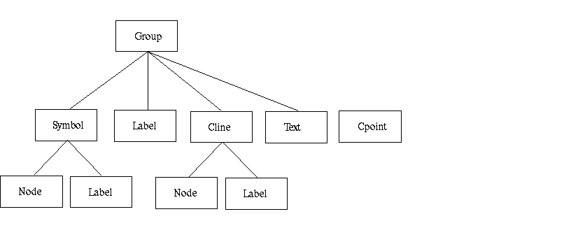
As with other CADMATIC modules, there are both "visible" and "administrative" objects in DG.
Groups
- Links together a set of connection lines and/or symbols.
- Labels can be assigned to group objects.
Symbols
- A visual object type used for visualizing diagram symbols, such as valves, pumps, and vessels.
Connection lines
- A visual object type used for connecting symbols with a polyline.
- Visualizes pipe runs and instrument lines.
Labels
- A visual object type used for visualizing some properties of groups, symbols and connection lines. Data is extracted from the external database, formatted, and printed via a suitable 2D symbol.
- Typically contain pipeline IDs, position IDs, and such.
Text
- A visual object type used for visualizing text.
Connection points
- Defines the point where two DG objects (either connection lines or symbols) are connected together.
Connection nodes
- Nodes are the link in connection lines and symbols to connection points.
- Two nodes (one in both connected objects) reference one connection point.
The DG Object Structure

Drawing attributes
Drawing attributes are assigned as properties to the objects. These are the same as those of the drafting module objects.