Define systems
Besides objects like vessels and valves, a diagram also includes some grouping objects: systems, pipelines, and instrument tags. A system is the basic group objects belong to. Every diagram object belongs to some system. The default system is DEFAULT_SYSTEM.
Now it is time to define some new piping systems. In this case you have four systems:
-
One system for all equipment
-
Two systems for piping
-
One system for all instrumentation
Systems and pipelines are common for the whole CADMATIC project. The data needed in P&ID is stored in the database as well as in the COS objects system and pipeline.
You can define systems in two ways:
-
Method one:
-
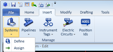
Select Insert > Systems > Define.
-
Click Create to accept the prefilled system name.
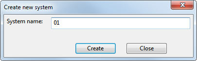
The format of the system name varies among organizations. In this setup, systems are by default named with a two-digit number (01, 02, 03...), but you can as well enter any proper name.
-
-
Method 2:
-
Select File > Environment > Systems and lines.
-
Change the permission of use to allow to use the system in both P&ID and Plant Modeller.
-
Define more systems
Define more systems using the following details for each:
|
Purpose |
Color |
Line widths |
|
|---|---|---|---|
|
Steam for the second piping system |
Cyan |
0.25, 0.25, 0.70 |
02 |
|
Equipment |
Green |
0.35 |
Equip |
|
Instruments |
Dark violet |
0.13 |
In |
Note: Use a short name for the instrumentation system because of the limited space for a position ID in the instrumentation symbols.
About system properties
In the CADMATIC P&ID application, the diagram objects (usually) inherit the drawing properties (color, line width, layer, and so on) from their system. After the system is defined you can assign selected objects to that system.
Note: You can define if the drawing attributes follow the current system or if they are fixed. However, it is recommended to use drawing attributes according to the current system.
The system record stores all per-system data. In this setup, there is only a little data for the drawing properties.
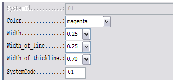
Do the following:
-
For Color, select magenta.
-
For Width, select 0.25.
-
For Width_of_line, select 0.25.
-
For Width_of_thickline, select 0.70.
-
For SystemCode, enter 01 as the value.
The attributes affect the drawing in the following ways:
-
Width defines the thickness for symbols.
-
Width_of_line defines the thickness for connection and auxiliary lines.
-
Width_of_thickline defines the thickness for primary lines.
-
If you set Width_of_line to 0, it uses the same thickness as the symbols.
-
If you set Width_of_thickline to 0, it uses same thickness as connection lines.
-
SystemCode is the default prefix for pipelines.
About cut level
Do the following:
-
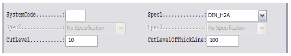
For CutLevel, enter 10 as the value. This determines the cut level for auxiliary and secondary lines.
-
For CutLevelOfThickLine, enter 100 as the value. This determines the cut level for primary lines.
-
For Spec1, select DIN_H2A. This is the default piping specification when defining pipelines.
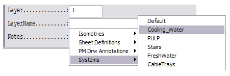
About layers
Do the following:
-
Right-click the LayerName field to select a convenient layer for the system objects.
In practice, the project administrator has to create layers by selecting File > Environment > All Library and Project > Project / Configuration / Common / Drawing export configuration before you can select them for the system.
The administrator can create a new group for layers. To simplify the drawing exportation, you can map all piping systems to the same layer Piping.
Do the following:
-
Leave the LayerName field empty.
-
Click OK.
-
Click Cancel if you do not want to create more systems.
The new system is now updated to the COS Project Database.