The point cloud work process
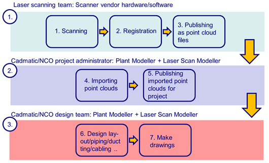
When working with point clouds in Plant Modeller, there are three main roles in the work process:
These roles are described below.
Laser scanning team
For the laser scanning team, the process goes as follows:
-
The team collects the data by using laser scanning equipment at the target site, producing one file per scan. The files are aligned and transformed into one coordinate system.
-
The registration is done using the software provided by the scanner vendor.
-
The registered data is published in a format that can be read into Plant Modeller— see Point cloud formats. The published data includes the exact location of each scanner.
As an example, in the case of Faro™ scanners and software, the following files are forwarded:
-
Point clouds in .xyz format files
-
Locations of the scanners in the file ScanPositions.txt
After the registration, you can publish the data from the native Faro files with the Faro SCENE LT™ software or similar.
Note: The published point cloud files need to be per-scanner files, without point decimation. In the context of Plant Modeller. Do not combine the point clouds as decimated "slice-of-plant" files.
CADMATIC project administrator
For the CADMATIC project administrator, the process goes as follows:
-
The project administrator uses the Point Cloud Manager tool of Plant Modeller to import the point cloud files into CADMATIC format binary point cloud data files (*.cpd). The import requires the Point Cloud Importer license.
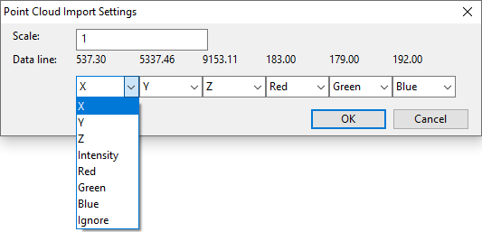
Typically, an ASCII point cloud file format is more like a family of formats: with various export options, you can create multiple combinations of data from the exporting software (e.g. Scene LT) under a single format selection (e.g. .xyz). The number of data items generated per row, as well as the order of these items on each row, can vary. However, the importer can only utilize the following data per row:
-
X
-
Y
-
Z
-
R
-
G
-
B
-
Intensity
At the beginning of the import, the Point Cloud Import Settings dialog opens.
-
Scale – Select the scale.
-
Data line – Shows an example data row from the input file.
Define the function of each data item to map the data correctly in the import.
-
-
During the import process, you can apply a transformation to the imported point clouds (Relocate) to set a new origin or to rotate the point clouds. This is seldom needed, but sometimes the coordinate system origin or main coordinate axis rotations set in the registration process are not those the designers want to use in 3D modeling.
-
When all point clouds are imported and checked, the project administrator publishes the binary CADMATIC format point cloud data files to the project for the designers to load and use.
CADMATIC designers
For the CADMATIC designers, the process goes as follows:
-
CADMATIC designers copy the binary .cpd files to their local point cloud file directories.
At design time, they utilize the special point cloud related functions in Plant Modeller:
-
Point Cloud Manager tool
-
3D views
-
3D navigation commands
-
-
The end products of the design work are the same as in normal design projects: documents, BOM lists, and eBrowser models.
eBrowser can visualize point clouds that are stored in CADMATIC format.