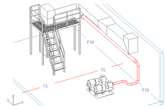
Pipeline 01
When routing the first pipeline, you take advantage of planes which are named TT (tank top), CL and F10. F## is numbered according to the modeling area. For system AA, the plane is named F10, for system BB, it is named F20, and so on.
Many of the pipes in the following exercises will connect to this pipe, so it is important that you route this pipe correctly.
In this exercise, you learn how to:
-
Start routing at a connection.
-
Define coordinates for the pipe.
-
Add an elbow by adding and removing a segment.
-
Add a reducer to define a direction.
-
Add flanges.
Note: Before routing, it is recommended to read about Working with views.
Start at a connection and define the pipeline
Start the routing at a connection and select definitions for the pipeline.
Do the following:
-
Select Piping > Route pipe.
-
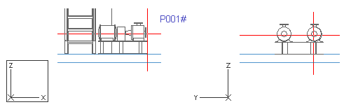
Move the cursor near the pump suction connection P001A.
-
Press Q to lock the cursor to that connection.
-
Press P to connect.
If the cursor is locked to a wrong connection point, press 5 and 6 to release the cursor, and press Q again to navigate once again to the pump connection.
Note: It is not necessary to press Q to lock cursor to the connection point of the pump, but it makes navigation easier because of the default hit distance of 400 mm. Pressing Q does not pick information (size, direction, compatibility) from the connection point and does not connect either, but pressing P does. However, the hit distance during navigating when pressing P is only 100 mm.
-
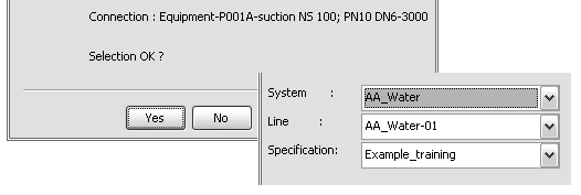
Click Yes to accept the connection point .
-
For System, select AA-Water.
-
For Line, select AA_Water-01.
-
For Specification, select Example_training.
-
Click Done.
You have now started routing a pipe at a connection and defined it.
Define the X,Y,Z coordinates for the first segment
When the start point has been defined by pressing P, the direction for the pipe segment is defined according to that connection point.
Next, you have to define the X, Y, and Z coordinates for the first pipe segment.
Do the following:
-
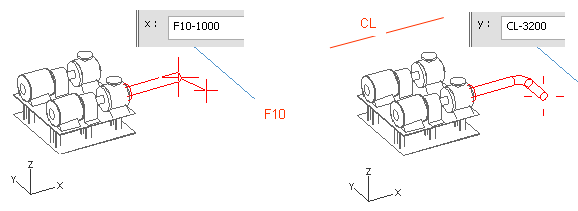
Press X to define the X coordinate.
-
For x, enter F10-1000 as the value.
When defining the values for the coordinates, note that the name of the plane is case-sensitive.
-
Click OK to accept the value.
-
Left-click or press Space to accept the point.
-
Press W to lock the cursor to the last point, which is the nearest pipe geometry point, to have the same X and Z coordinates in the original location and the next point.
You can release the cursor by pressing 5 and 6, or move the cursor to the original location by pressing Shift+R.
-
Press Y to define the Y coordinate.
-
For y, enter CL-3200 as the value.
-
Click OK.
-
Left-click or press Space.
-
Press W to lock the cursor to the nearest pipe geometry point.
-
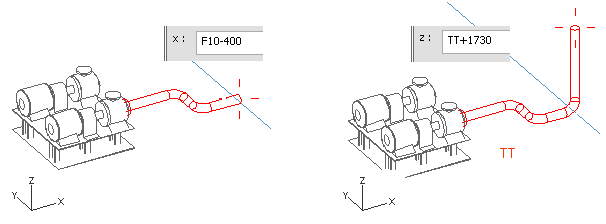
Press X to define the next X coordinate.
-
Enter F10-400 as the value.
-
Click OK and press Space to accept the point.
-
Press W.
-
Press Z to define the Z coordinate.
-
Enter TT+1730 as the value.
-
Click OK and press Space.
You have now extended the pipe using coordinates.
Add an elbow and reducer for Y direction
Next, you add an elbow to the pipe by routing the pipe into the right direction, and then removing the segment so that only the elbow remains.
Do the following:
-
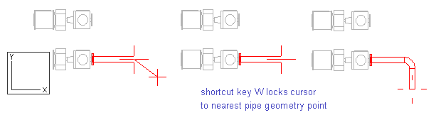
Press W.
-
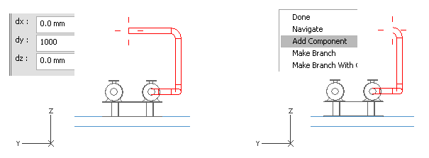
Press D to set a distance from the cursor in the Y axis.
-
For dy, enter 1000 as the value.
-
Press Space to accept the point.
-
Press U to remove the pipe segment.
The elbow in the pipe remains after you have removed the last pipe segment.
-
Right-click, and select Add Component.
-
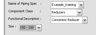
For Component Class, select Reducers.
-
For Functional Description, select Concentric Reducer.
-
For Size, select 150 - 100.
-
Click Done.
The reducer defines the direction for the next segment parallel to the Y axis. The cursor is also locked to the line. To release the cursor for navigation, press Shift+A. The direction for the pipe segment remains to what the reducer has defined.
-
Press Y.
-
Enter CL+3000 as the value.
-
Press Space.
You have now added an elbow and a reducer to the pipe.
Add a normal flange and blind flange
Do the following:
-
Right-click, and select Add Component.
-
Select Flanges with option Shorten Pipe.
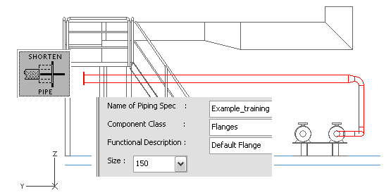
-
Click Done to accept the pipe.
Note: If you click No to the question Is the pipe ok?, the program cancels the previous segment. If you click Cancel, the whole pipeline is canceled.
-
Select Piping > Route pipe to start routing a new pipe.
-
Move the cursor near the end of the end of the previous pipe.
-
Press Q to lock the cursor to the flange.
-
Press P to connect the pipe to the flange.
-
Click Yes to accept the connection.
-
Select the System, Line and Specification values as shown in the picture below.
-
Click Done.
-
Press U to cancel the pipe segment.
-
Right-click, and select Add Component.
-
For Component Class, select Flanges.
-
For Functional Description, select Blind Flange.
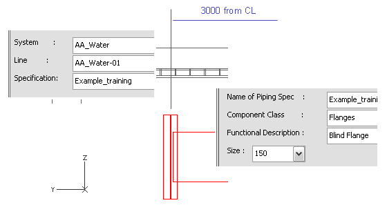
-
Click Done.
-
Press Enter to accept the pipe.
You have now added two different types of flanges to the pipe.
You have routed the first pipe starting from the pump suction connection and ending in two flanges.