Pipeline 10
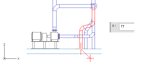
This pipeline starts with a branch from the run pipe. The Y coordinate is defined with the plane CL. The first segment is parallel to the negative Z axis and it ends 975 mm from the tank top, plane TT.
The direction for the next segment is defined with two angles. The X coordinate of the end point is defined with the plane F10, which locates at the edge of the tank top.
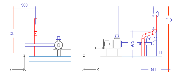
The last pipe segment is parallel to the Z axis and it ends at the tank top.
Do the following:
-
Select Piping > Route pipe.
-
Move the cursor inside the run pipe.
-
Press F11 to lock the cursor to the centerline.
-
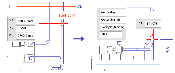
Press C to define the coordinates for the start point.
-
For y, enter CL-900 as the value.
-
Click OK.
Do not accept the start point.
-
Right-click, and select Create branch.
The run pipe should be highlighted. If a wrong pipe is highlighted, press Space until the selection is correct.
-
Press Enter to accept the run pipe when it is highlighted.
-
For System, select AA_Water.
-
For Line, select AA_Water-10.
-
For Nominal Size, enter 100 as the value.
-
Click Done.
-
Press Alt+Ctrl+Z to set the direction to the negative Z axis.
-
Press Space to accept the direction.
-
Press Z.
-
Enter TT+975 as the value.
-
Click OK.
-
Press Space.
-
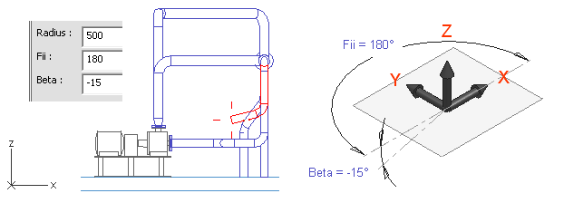
Press S to define the spherical coordinates.
-
For Radius, enter 500 as the value.
The segment has to be long enough to have an elbow.
-
For Fii, enter 180 as the value.
-
For Beta, enter -15 as the value.
-
Click OK.
-
Press Space.
-
Press U to cancel the previous pipe segment.
Only an elbow remains.
-
Press X.
-
Enter F10-900 as the value.
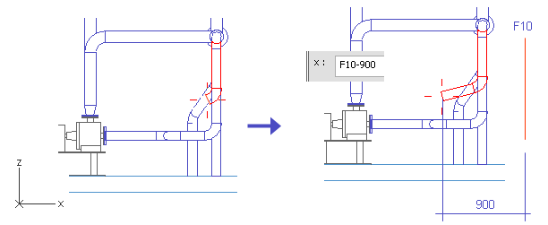
-
Click OK.
-
Press Space.
-
Move the cursor near the end of the pipe.
-
Press W.
-
Press Z.
-
Enter TT as the value.
-
Click OK.
-
Press Space.
-
Press Enter.
-
Click Yes.
You have now routed a pipe that starts from the run pipe with a branch, angles slightly at the middle and ends at the tank top.