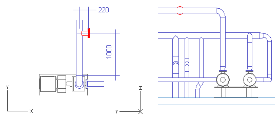
Pipeline 13
This pipeline starts with a branch from the pipeline AA_Water-04. It consists of a straight pipe segment and two flanges, a normal and a blind one. This exercise teaches you two particular techniques:
-
Dimensioning the branch from the centerline of the run pipe
-
Adding a blind flange into an existing pipe
Do the following:
-
Select Piping > Route pipe.
-
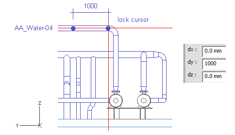
Move the cursor near the midpoint of the elbow on the pipeline AA_Water-04.
-
Press W.
-
Press D.
-
For dy, enter 1000 as the value.
-
Click OK.
Do not accept the point.
-
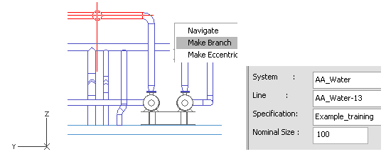
Right-click, and select Create branch.
-
Press Enter to select the run pipe when it is highlighted.
-
For System, select AA_Water.
-
For Line, select AA_Water-13.
-
For Nominal Size, enter 100 as the value.
-
Click Done.
-
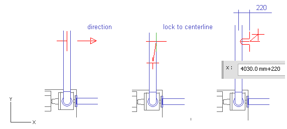
Press Alt+X to set the direction to the positive X axis.
-
Move the cursor inside the pipeline AA_Water-04.
-
Press F11.
Now, the length of the branch is evaluated from the centerline. Normally, it is dimensioned from the silhouette edge of the run pipe.
-
Press X.
-
Enter [the current value]+200 as the value.
-
Click OK.
-
Press Space.
-
Right-click, and select Add Component.
-
For Component Class, select Flanges.
-
For the method of placement of the flange, select Shorten Pipe.
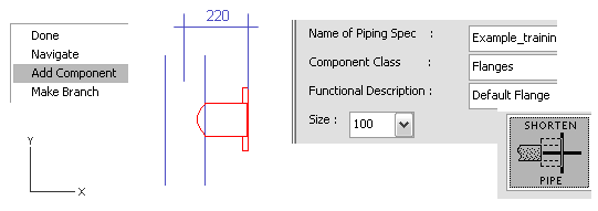
-
Click Done.
-
Click Yes.
-
Select Piping > Route Pipe.
-
Move the cursor near the end of the last pipe-end.
-
Press Q.
-
Press P to connect the pipe to the flange.
-
Click Yes.
-
Select the same values for System and Line as previously.
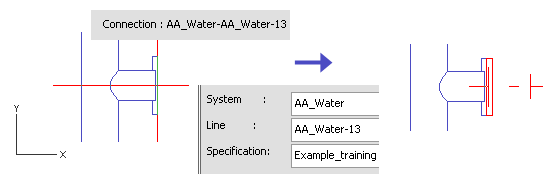
-
Click Done.
-
Press U to cancel the pipe segment.
-
Right-click, and select Add component.
-
For Component Class, select Flanges.
-
For Functional Description, select Blind Flange.
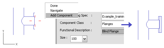
-
Click Done.
-
Click Yes.
You have now routed a short pipe that branches from a run pipe and has two flanges at the end.