Electrical settings
|
|
Electrical tab > Settings group > Electrical |
|
|
File > Settings > Electrical settings |
In the Electrical settings, you can define general settings affecting the use of the application as well as toolset specific settings. The settings dialog automatically opens to the correct tab based on the drawing type of the current drawing; for example, if the drawing type is Multi-line diagram, the dialog opens to the Schematics tab. If there are no settings for the current drawing type, the dialog opens to the General tab.
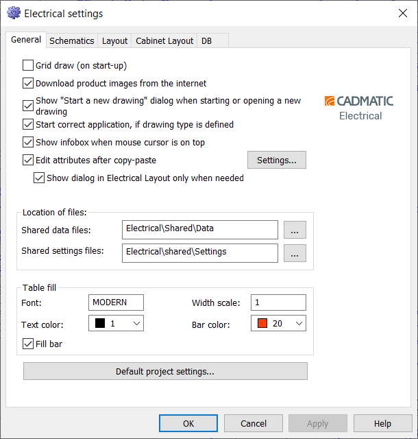
General settings
In the general settings, you can define how you want the application to work overall. These settings are common for all toolsets.
The general settings are saved in the scads.ini file in application's installation directory.
-
Grid draw (on start-up) – Select this if you want the grid dots to be shown in the drawing area.
-
Download product images from the internet – Select this if you want the product images to be downloaded from the internet.
-
Show "Start a new drawing" dialog when starting or opening a new drawing – Select this if you want the Start a new Electrical drawing dialog to be shown when opening or starting a new drawing. In the dialog, you can, for example, define the drawing type.
-
Start correct application, if drawing type is defined – Select this if you want the application to automatically change based on the drawing type. If this is not selected, the application is never changed even if the drawing type has been defined for the drawing.
-
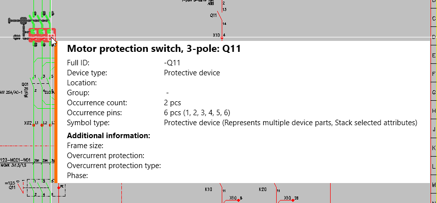
Show infobox when mouse cursor is on top – Select this if you want the information box to be shown when you take your mouse pointer on an element. The information box shows the element properties:
-
Edit attributes after copy-paste – Select this if you want the attribute editor to be opened when you paste a copied symbol into the drawing. You can define the information to be copied by default by clicking Settings.
 Show/hide details
After clicking Settings, the Paste dialog opens. By default, all information is selected to be copied. Click the check boxes for the information you do not want to be selected by default when copying objects.
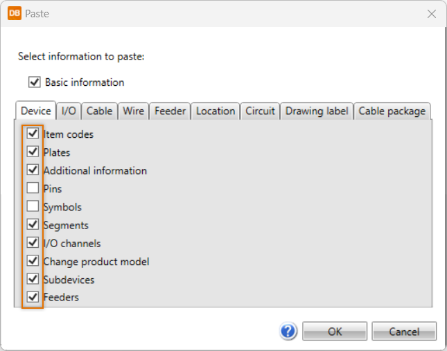
The default selections can be changed in connection with pasting.
- Show dialog in Electrical Layout only when needed – Select this if you want the attribute edit dialog to open in arrangement drawings only when there are elements that usually require user interaction, such as distribution boards and groups.
For more information, see Edit values for copied objects
-
Shared data files and Shared setting files – Define where common data such as table definition files (.tau) and setting files are located. The Shared data files change is only applied after you restart the application.
-
Table fill – Define the settings related to filling tables, such as highlight color and font.
-
Default project settings – Define the default settings for new projects. You can edit all the same settings that actual projects have. Settings are saved to the EDBUser.mdb database which is located in the Electrical\Shared\Data folder.
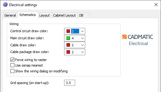
Schematics settings
In the Electrical settings dialog, you can define the settings for the Schematics toolset on the Schematics tab. The settings are saved in the scads.ini file in the CADMATIC directory.
-
Wiring
-
You can set the wire drawing colors as desired. However, it is recommended to use the same drawing colors than in schema symbols.
-
Control circuit draw color – 2 (red)
-
Main circuit draw color – 4 (green)
-
Cable draw color – 2 (red)
-
Cable package draw color – 2 (red)
-
-
Force wiring to raster – If this setting is enabled and drawing is not started from a wiring point, starting point is moved to the raster.
-
Use osnap nearest – When this setting is enabled, snap will force points to the nearest point of object. This is useful when wiring from boundary to boundary, for example, instead of from wiring point to wiring point.
-
Show the wiring dialog on modifying (Electrical Premium) – When this setting is enabled and you click a wire, cable or cable package, it is selected and the Wiring window opens. When this setting is disabled, the wire, cable or cable package is selected but the Wiring window will not open.
-
-
Grid spacing (on start-up) – When starting the application, the grid spacing will be set according to this setting. It is recommended to use 3.5 mm, as that is how the symbols have been drawn.
Note: If the module spacing is 2.5 mm, the grid spacing should be 2.5 mm.
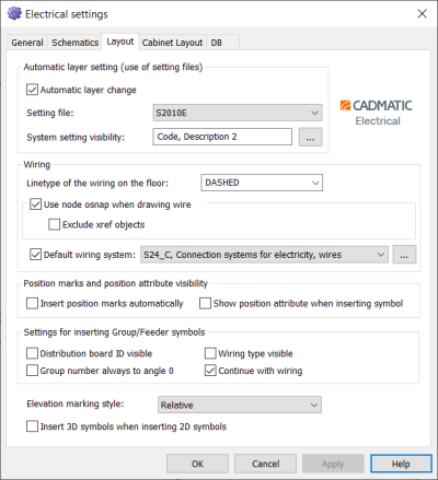
Layout settings
In the Electrical settings dialog, you can define the settings for the Layout toolset on the Layout tab. The settings are saved in the scads.ini file in the CADMATIC directory.
-
Automatic layer settings (use of setting files)
-
Automatic layer change – When this is selected, the layer to be used is defined according to the setting file, which means that symbols, for example, will be inserted to the layer defined in the settings file. When this is not selected, symbols and wiring will be inserted to the active work layer. For more information on setting files, see Setting files.
-
Setting file – The setting file to be used.
-
System setting visibility – Select which system information you want shown: name, code, layer, description and description 2.
-
-
Wiring
-
Linetype of the wiring on the floor – Line type for ground wires (elevation below 0mm).
-
Use node osnap when drawing wire – The symbols in Layout always include wiring points. When this setting is selected, wires will be correctly connected.
-
Exclude xref objects – When using node osnap, wiring points found from reference drawings will be ignored.
-
Default wiring system – This system is used when application cannot define the wiring system automatically from symbols that are being wired. You can pick the system from the drawing by clicking the
 button.
-
-
Position marks and position attribute visibility
-
Insert position marks automatically – When selected, position marks will be inserted for lighting fixtures and heaters with position defined when inserting the symbols.
-
Show position attribute when inserting symbol – When selected, position attributes will be shown after insertion for lighting fixtures and heaters with position defined.
-
-
Settings for inserting Group/Feeder symbols
-
Distribution board ID visible – Select this if you want the distribution board ID to be shown. By default, the ID is not shown.
-
Wiring type visible – Select this if you want the wiring type to be shown. By default, the wiring type is not shown.
-
Group number always to angle 0 – Select this if you want to set group marking's group number to angle 0 when inserting a new group occurrence.
-
Continue with wiring – Select this if you want to continue with wiring after insertion.
-
-
Elevation marking style – You can select elevation style from relative (from the space's floor), absolute (from the site origo) or both. Style will be used as a default on elevation markings that do not have style specified.
-
Insert 3D symbol when inserting 2D symbols – If a 2D symbol has its 3D equivalence defined, it will be placed during the 2D symbol insertion.
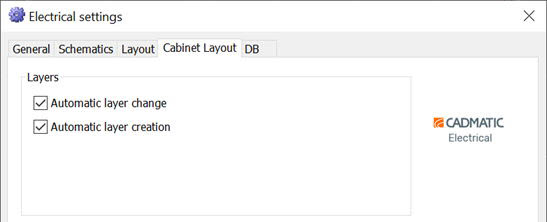
Cabinet Layout settings
In the Electrical settings dialog, you can define the settings for the Cabinet Layout toolset on the Cabinet Layout tab. The settings are saved in the scads.ini file in the CADMATIC directory.
-
Automatic layer change – When selected, symbols are inserted automatically to the layers the application uses.
-
Automatic layer creation – When selected, the layers that the application uses are created automatically when starting a new drawing.
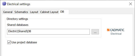
DB settings
In the Electrical settings dialog, you can define the settings for the DB tool on the DB tab. The settings are saved in the scads.ini file in the CADMATIC directory.
-
Shared databases – Defines the location of shared databases. By default, the shared databases are located in Electrical\Shared\DB in the CADMATIC directory.
-
Use project database – When this setting is enabled, the database information will be updated while opening the drawing. This setting also enables communication between different drawings in the project.