Draw area boundaries
Let's draw boundaries around the safety switch and the motor.
Note: The boundaries only indicate that the safety switch and the motor do not belong to the distribution board +MCC1. We only draw these boundaries to make the drawing easier to read; the application will not take it into account in any way. Components have been excluded from the distribution board with an ID: for example, =123-M01 means that the motor M01 belongs to =123 but is not a component of +MCC1.
Do the following:
-
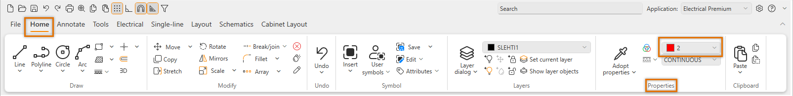
Select Home tab > Draw group > Line.
-
In the Properties group, select the color 2 (red) from the drop-down menu.
-
Below the color drop-down menu, select DASHDOT as the line type.
-
Draw the lines.
Note: After drawing, change the line type back to CONTINUOUS.
 Previous Previous |
Next

|