Schematics tab > Wiring group > ![]() Edit menu > Define internal wirings automatically
Edit menu > Define internal wirings automatically
With this function, you can define internal wirings (= lines/polylines) automatically. Wires connected with this function are dynamic i.e. automatically updated if the connection information at either end change and the databases are updated via the drawing.
The dialog lists internal wires with no wire data. Function identifies lines/polylines as internal wires when both ends of are situated in the same location i.e. have the same electrical position.
With the options in the Show section, you can filter what is shown:
-
Location – Wires from the selected location or all locations are shown.
-
Sheet – Wires from the selected sheet or all sheets are shown.
-
All wirings – All internal wires are shown.
-
Main circuit wirings – Only main circuit wires are shown. The function identifies main circuit wires by their color which is defined in Electrical settings. Green is the default color for main circuit wires.
-
Control circuit wirings – Only control circuit wires are shown. The function identifies control circuit wires by their color which is defined in Electrical settings. Red is the default color for control circuit wires.
-
'Busbars' – Lines that have been defined as busbars are shown.
-
Not wire – Lines not defined as wires are shown.
-
Undefined wires – Wires drawn with wire drawing functions of the Schematics toolset without wire data.
-
Internal wires – Internal wires are shown.
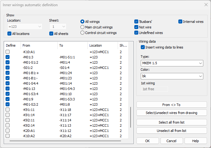
The Define column shows the wires about to be defined. They are also shown in blue in the drawing:
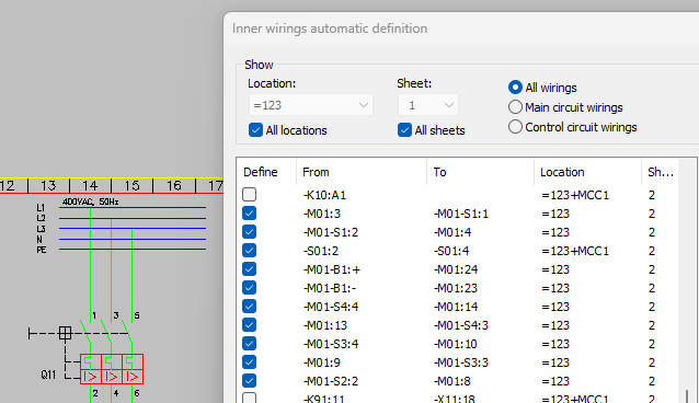
If wiring information from either end of the wire is missing (K10:A1 in the first image, for example), the wire is not selected to be defined. Furthermore, adjacent terminal blocks ( X10:1 and X10:2, for example) are not selected to be defined either.
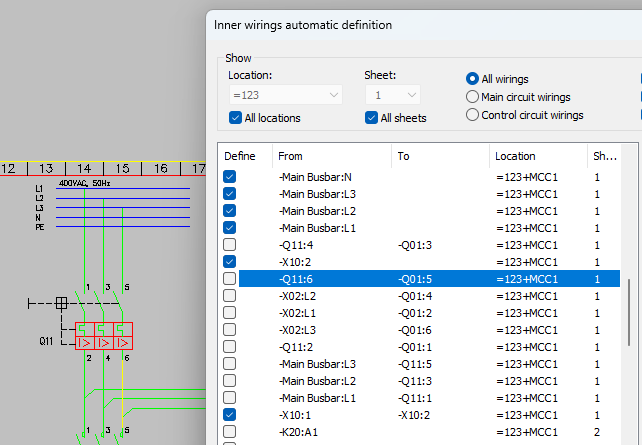
When you select a wire in the list, it is shown in yellow in the drawing:
With Select all from list, you can give all the wires the Define setting and with Unselect all from list you can remove it from them.
With From <> To, you can reverse the From and To information for the selected wire.
Select/unselect wires from drawing – Select the wires you want to add to the list or remove from the list.
In the Wiring data section, you can define whether to add wiring data for the lines. Furthermore, you can define the wire type and color. The wires will numbered consecutively starting from the first wiring number.
You can also open the function by selecting the lines/polylines in the drawing, right-clicking and selecting Automatic defining of internal wirings. The dialog then lists only the selected wires:
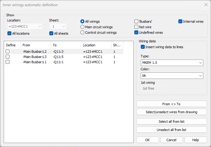
Otherwise, the definition function works as explained.