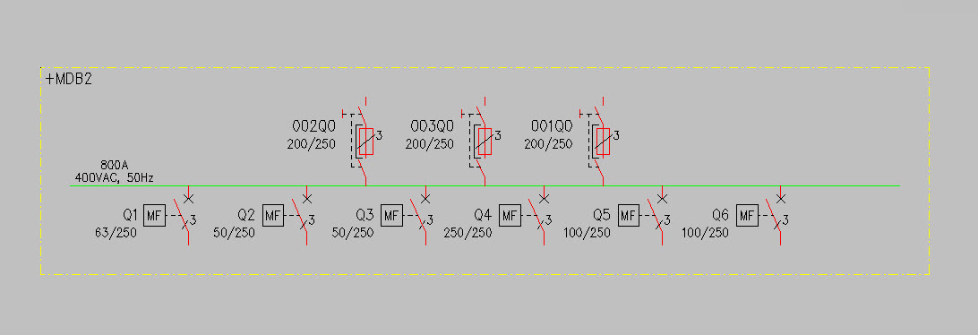
Draw busbars with feeders and location boundaries
With the Draw busbar into the drawing function in the Distribution boards and feeders project tree, you can insert the busbar, its incoming and outgoing feeders and location boundaries, if necessary, all at once.
Do the following:
-
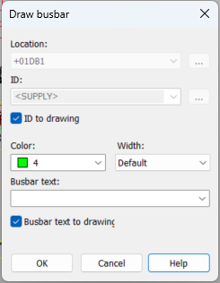
Select the Draw busbar into the drawing function in the project tree. The Draw busbar dialog opens.
-
Change the information as necessary.
- It is not possible to change the location or the ID.
-
You can select 0.25, 0.35, 0.50, 0.70, 1.00, 1.40, or 2.00 as the line width.
-
Click OK.
-
Indicate the start point for the busbar.
-
Indicate the end point for the busbar.
-
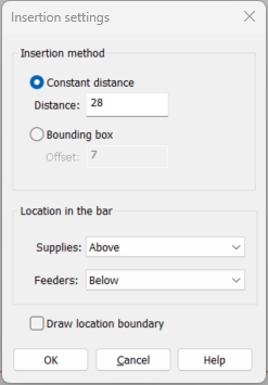
Press Enter. The Insertion settings dialog opens.
-
Define the insertion method and location for the feeders.
-
If you want to insert location boundaries, select Draw location boundary.
-
Click OK. The busbar with its feeders and possibly location boundaries has now been added into the drawing.