You can draw a terminal strip in the project from the project tree, or via the terminal strip settings dialog. Via the project tree, you can also create a new terminal strip and draw it.
You can define the layout of the terminal strip and the end clamp in the settings.
Learn more:
Draw an existing terminal strip
Do the following:
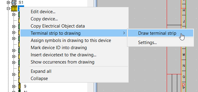
- In the device project tree, right-click the terminal strip and select Terminal strip to drawing > Draw terminal strip.
- Indicate the beginning of the terminal strip. If you want to split the terminal strip to multiple parts, keep Ctrl key pressed down when indicating the beginning of the strip.
- Indicate the maximum length for the first part of the terminal strip. The function continues by inserting the rest of the terminal strip. You can also split the remaining part of the strip the same way as the first part.
Alternatively, select Settings, define the desired settings for the terminal strip and then draw the strip by clicking Draw terminal block. For more information on the settings, see Define drawing settings and draw a terminal strip based on them.
Create and draw a new terminal strip
Do the following:
-
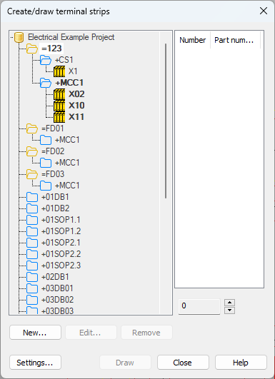
In the device project tree, right-click a location or an electrical position and select Draw terminal strip. The Create/draw terminal strips dialog opens.
-
Click New. The Define terminal blocks dialog opens.
-
Define the terminal block details.
-
Click OK.
-
Define the drawing settings:
-
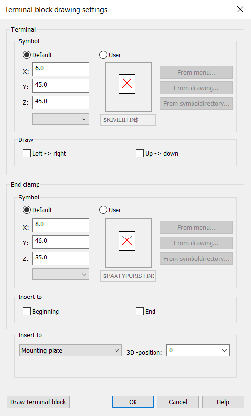
Click Settings. The Terminal block drawing settings dialog opens.
-
In the Terminal section, do the following:
-
Select Default to draw the block as a rectangle with given measures, or select User to use your own symbol. If you select User, select whether to select the symbol from a menu, from the drawing, or from the symbol directory:
-
From menu – In the Symbol selection dialog, double-click the symbol you want to select. The Symbol selection dialog closes, and the symbol you selected is shown in the preview pane. For more information on the Symbol selection dialog, see Symbol selection.
-
From drawing – Select the desired symbol in the drawing.
-
From symbol directory – Select the desired symbol from the symbol directory.
-
-
If you always want to draw from left to right or from top to bottom regardless of the symbol insertion angle, select the desired option below Draw.
-
-
In the End clamp section, do the following:
-
Select Default to draw the block as a rectangle with given measures, or select User to use your own symbol. If you select User, select whether to select the symbol from a menu, from the drawing, or from the symbol directory:
-
From menu – In the Symbol selection dialog, double-click the symbol you want to select. The Symbol selection dialog closes, and the symbol you selected is shown in the preview pane. For more information on the Symbol selection dialog, see Symbol selection.
-
From drawing – Select the desired symbol in the drawing.
-
From symbol directory – Select the desired symbol from the symbol directory.
-
-
Below Insert to, select whether to insert the end clamp to the beginning or to the end of the terminal strip or to both ends.
-
-
Below Insert to, select where the terminal strip will be mounted: Mounting plate, Door/cover or Back. You can also add offset to generated 3D symbol by adjusting 3D-position (affects Z-coordinate).
-
Click OK.
-
-
Draw the terminal strip by clicking Draw and indicating the insertion point.
Via the Create/draw terminal strips dialog, you can also
-
Draw an existing terminal strip by selecting it and clicking Draw.
-
Add terminal blocks for a terminal strip by selecting the desired terminal strip and clicking Append.
-
Edit the ID and numbering of a terminal strip by selecting the desired terminal strip and clicking Edit.
Define drawing settings and draw a terminal strip based on them
Do the following:
-
In the device project tree, right-click the terminal strip and select Terminal strip to drawing > Settings. The Terminal block drawing settings dialog opens.
-
In the Terminal section. do the following:
-
Select Default to draw the block as a rectangle with given measures, or select User to use your own symbol. If you select User, select whether to select the symbol from a menu, from the drawing, or from the symbol directory:
-
From menu – In the Symbol selection dialog, double-click the symbol you want to select. The Symbol selection dialog closes, and the symbol you selected is shown in the preview pane.
-
From drawing – Select the desired symbol in the drawing.
-
From symbol directory – Select the desired symbol from the symbol directory.
-
-
If you always want to draw from left to right or from top to bottom regardless of the symbol insertion angle, select the desired option below Draw.
-
-
In the End clamp section, do the following:
-
Select Default to draw the block as a rectangle with given measures, or select User to use your own symbol. If you select User, select whether to select the symbol from a menu, from the drawing, or from the symbol directory:
-
From menu – In the Symbol selection dialog, double-click the symbol you want to select. The Symbol selection dialog closes, and the symbol you selected is shown in the preview pane.
-
From drawing – Select the desired symbol in the drawing.
-
From symbol directory – Select the desired symbol from the symbol directory.
-
-
Below Insert to, select whether to insert the end clamp to the beginning or to the end of the terminal strip or to both ends.
-
-
Below Insert to, select where the terminal strip will be mounted: Mounting plate, Door/cover or Back. You can also add offset to generated 3D symbol by adjusting 3D-position (affects Z-coordinate).
-
Draw the terminal strip by clicking Draw and indicating the insertion point.