Draw additional information boundaries
|
|
Single-line tab > Other functions group > Additional info boundary |
| Layout tab > Other functions group > |
|
| Schematics tab > Other functions group > |
With this function, you can define devices to belong to a certain space or electrical outlets to belong to certain classes or between specific boundaries, for example. You can define multiple boundaries which can also be nested. In nested boundaries, the smaller one is primary. Overlapping boundaries should be avoided as it might then be difficult to tell in which bounded area the items belong to.
You can also add additional information to reference drawings with boundaries that create the additional information.
-
After the additional information boundaries have been created, the additional information does not automatically affect the additional information of the parent object inside the boundaries, other than by preventing the deletion of that additional information. In other words, changing the values for the additional information boundaries later does not affect the values of additional information already added.
-
If the reference drawing file is added to the project, all the project's additional information is available and can then be edited like any other information defined for devices.
-
If project-specific additional information is not used, the reference drawing file does not need to be in the project.
Do the following:
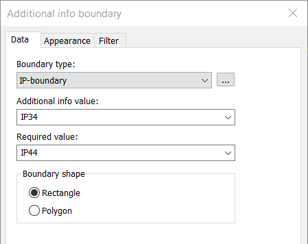
- Select the desired boundary type.
- Enter the boundary value, or select it from the drop-down menu.
- Enter the required value, or select it from the drop-down menu. The required value is saved to the boundary symbol's E_SYMBTXT2 attribute.
- Select the boundary shape. Boundaries can be drawn as a rectangle or polygon that allows any form for the bounded area.
- If necessary, define the appearance:
- Select the Appearance tab.
- If necessary, select boundary color and line type. By default, the color and line type come from the settings file.
- If you want to add a background symbol for the boundary, select Show symbol and define the symbol or a raster image:
- If you want to add a symbol, do the following:
- Select the Symbol option.
- If necessary, select a new color from the drop-down menu.
- If you want to scale the symbol, select the scaling method from the Scaling drop-down menu.
- Click Select symbol or the preview pane.
- Select how you want to add the symbol:
- Select from drawing – Indicate the symbol in the drawing.
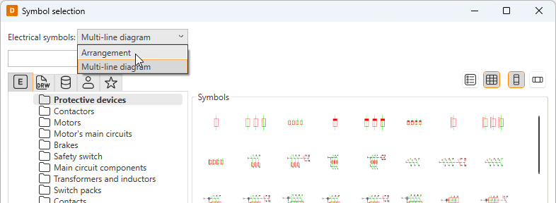
- Select from menu – Select the symbol in the Symbol selection dialog (see Symbol selection). By default, the symbols are shown based on the drawing type but you can select another drawing type (multi-line diagram or arrangement drawing) from the drop-down menu.
Click OK. The symbol you selected is now shown in the preview pane.
- If you want to add a raster image, do the following:
- Select Raster image. The Select symbol button changes to Select image.
- Click Select image and Select from disk.
- Select the desired image. The image will be scaled to fit the boundary while keeping the image aspect ratio unchanged. By default, raster images are saved to the Attachments sub-directory in the project directory.
- If you want to add a symbol, do the following:
- If you want to define a background fill color, select Boundary background color and then the desired color.
- Select whether to place the marking text inside or outside the boundary, and select the color.
- Click OK.
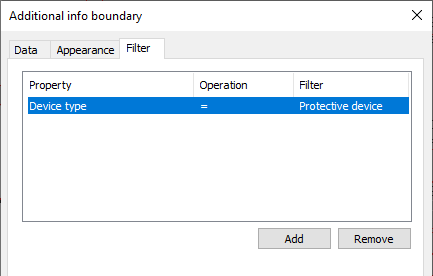
- If necessary, define the filters:
- Select the Filter tab.
- Define the desired information.
- Device type – A device type (e.g. protective device) or a negative filter with exclamation mark which excludes the defined device type.
- System – A system (e.g. S241) or a system mask (e.g. S2), alternatively a negative filter with exclamation mark which excludes the defined system (e.g. !S241).
- Elevation – An elevation value (e.g. 1500), a smaller or greater than value (e.g. <1500 or >1500), or a range (e.g. 1000-1500).
- Click OK.
- Draw the boundary into the drawing.
If necessary, you can add and edit the boundary types.
If a required value has been defined in the additional info boundary but the device inherits additional information from a product model, the inherited information is copied as the object's own additional information (the required value defined for the additional info boundary cannot be saved to the additional information of product model / cable definition / product information).
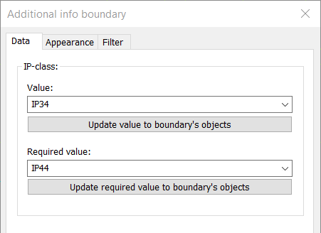
You can update both the boundary value and the required value to the objects by right-clicking the boundary and selecting Boundary properties.
Add and edit additional information boundary types
To create a new boundary type, do the following:
-
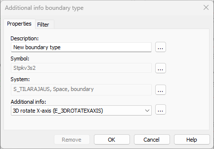
From the Boundary type drop-down menu, select New boundary type. The Additional info to boundary type dialog opens.
-
Enter the desired description.
-
Select the symbol by clicking the
 button next to the Symbol field.
 -
Select the system by clicking the
button next to the System field. -
Select the type of additional information from the drop-down menu. You can go to additional information management by clicking the
button. -
Click OK.
You can edit existing additional information definitions by clicking the ![]() button next to the Boundary type field. The drawing needs to be in the project.
button next to the Boundary type field. The drawing needs to be in the project.