|
|
Electrical tab > Settings group > Storey |
If there is more than one storey in a building, the drawings for each storey are defined in the storey settings. In addition, storey data is stored in the settings. The storey settings also affect the quantity
calculations (vertical cableways),
The storey settings are common for the whole project.
The settings are hierarchical: a storey is linked to a building, and a building to a building site. The tree on the left side of the dialog displays the current hierarchy.
After defining the storey settings, you can move from one storey to another with the PageUp and PageDown keys or with the Storey up and Storey down functions (available in the Storey menu). If there is more than one file defined for a storey, these functions move to the upper or lower file in the same planning area.
Learn more:
Manage sites
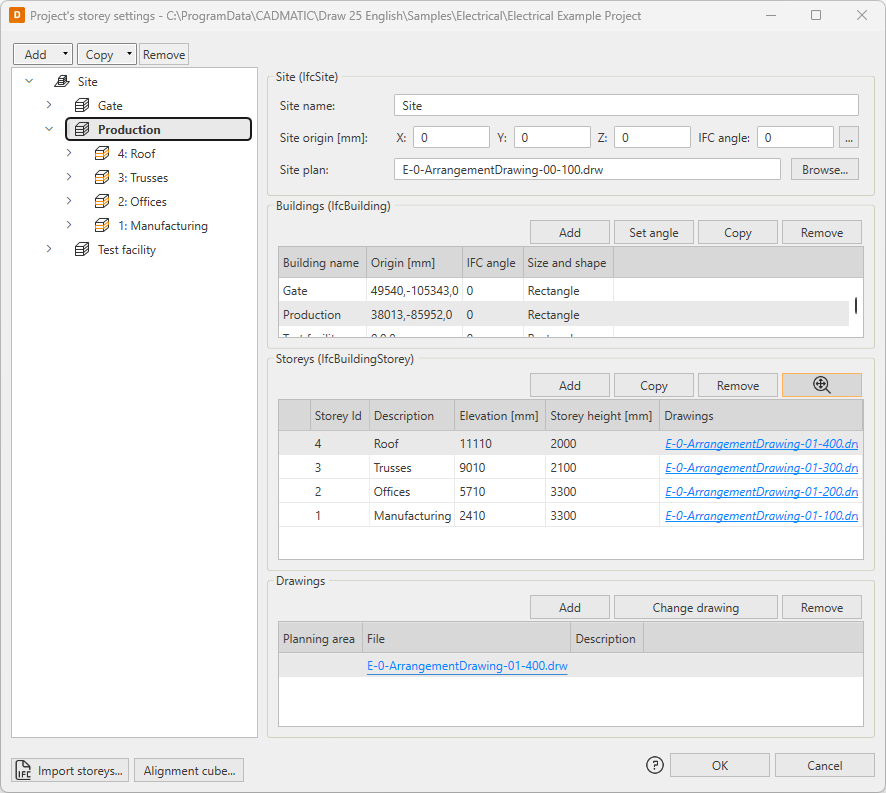
The Site section tells the name of the building site, origin, IFC angle and possibly the file name of the site plan.
-
Origin is usually the coordinate of the bottom left corner of the building site (top view).
-
You can define the IFC angle to be used in the IFC model either by entering it into the field or by clicking the
 button and indicating two points.
 -
You can define the site plan by clicking Browse.
Note: Site plan must be located in the project folder.
The site information corresponds to the IfcSite tag in the generated IFC file.
Manage buildings
The storey settings can include multiple buildings. Name, origin, IFC angle, and informal shape and size can be defined to each building.
-
Origin is usually the coordinate of the bottom left corner or the building (top view). The origin is relative to the site origin.
-
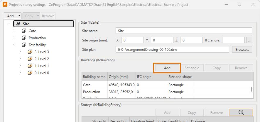
You can add a new building for a site as follows:
-
In the Buildings section, click Add.
-
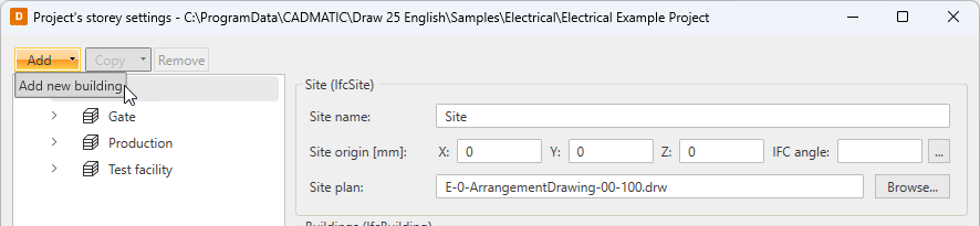
Select the site in the tree, click Add and select Add new building.
-
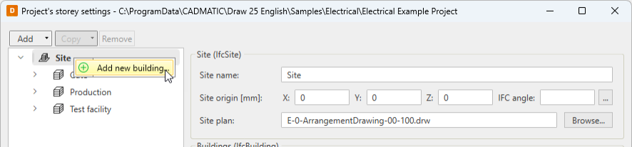
Right-click the site in the tree, and select Add new building.
-
-
You can also add a building by copying as follows:
-
In the Buildings section, select the building you want to copy and click Copy.
-
Select the building in the tree, click Copy and select Copy building.
-
Right-click the building in the tree, and select Copy building.
Then edit the information as necessary.
-
-
You can edit building information by selecting the desired cell and entering a new value.
-
You can remove an existing building as follows:
-
In the Buildings section, select the building you want to remove, click Remove and confirm removal with Yes.
-
Select the building in the tree, click Remove and confirm removal with Yes.
-
Right-click the building in the tree, select Remove building and confirm removal with Yes.
-
Note: Removing a building also removes any storeys defined for that building.
The building information corresponds to the IfcBuilding tag in the generated IFC file.
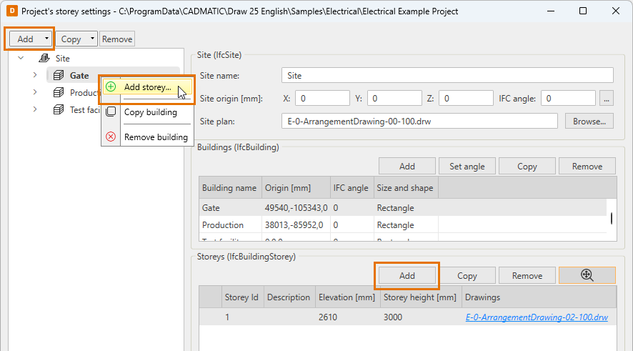
Manage storeys
The Storeys section stores the actual storey information that connects drawings to the storeys. A single drawing can only include one storey.
-
The columns in the section are the following:
-
Storey Id – Numeric or alphabetical ID for the storey, for example G, 1, 2, 3.
-
Description – Informal description of the storey, for example Ground floor, 1st floor, 2nd floor.
-
Elevation – Elevation of the storey floor. Elevation is relative to the site and building origin.
-
Storey height – Full height of the storey including intermediate floor in millimeters.
-
Drawings – A link to the drawing file corresponding each floor. There can be several drawing files for one storey, or you can decide not to add the file when adding a storey. If there is more than one file defined for a storey, the planning area information separates them from each other. The Storey up and Storey down functions move to the upper or lower file in the same planning area.
-
-
You can add a new storey for a building as follows:
-
In the Storeys section, click Add.
-
Right-click the building in the tree, and select Add storey.
-
Select the building in the tree, click Add and select Add storey.
-
-
You can also add a storey by copying as follows:
-
In the Storeys section, select the storey you want to copy and click Copy.
-
Select the storey in the tree, click Copy and select Add storey without drawings.
-
Right-click the storey in the tree, and select Copy storey.Then edit the information as necessary.
-
-
You can edit storey information by selecting the desired cell and entering a new value.
-
You can remove an existing storey as follows:
-
In the Storeys section, select the storey you want to remove, click Remove and confirm removal with Yes.
-
Select the storey in the tree, click Remove and confirm removal with Yes.
-
Right-click the storey in the tree, select Remove storey and confirm removal with Yes.
-
-
With the
 (Storey zoom) button selected, you can move from one storey to another and the program will zoom the view as it was in the previous storey. When using this setting it is important
that the storeys are drawn to the same coordinates.
(Storey zoom) button selected, you can move from one storey to another and the program will zoom the view as it was in the previous storey. When using this setting it is important
that the storeys are drawn to the same coordinates.
The storey information corresponds to the IfcBuildingStorey tag in the generated IFC file.
Import stories
You can import storey settings to Electrical with an IFC model, and then edit the information or attach files related to the storeys. The Import storeys function will import all parts, i.e. sites, buildings, and storeys. However, the files attached to them will not be imported. Also note that if there are storey settings defined, they will be replaced when you select the IFC file.
Use alignment cube
With the alignment cube, you can view the location of the data model. You can add the alignment cube to one of your project's drawings, after which it is automatically available in all project drawings. If you need to move the alignment cube, you can insert it again in one of the project's drawings after which it will be updated to all drawings.
You can define the size, color and comment for the alignment cube. The insertion point is always in world coordinates, and it can be the origin, defined with coordinates, or picked from the drawing.
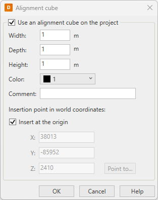
The alignment cube will always be included in the IFC export.