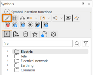
With the ![]() (Insert symbols on element) button, you can insert the desired number of symbols on an element
or at a certain distance via the Symbols window.
(Insert symbols on element) button, you can insert the desired number of symbols on an element
or at a certain distance via the Symbols window.
Do the following:
-
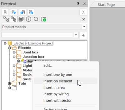
Select a symbol from a menu, the drawing or by entering symbol name.
-
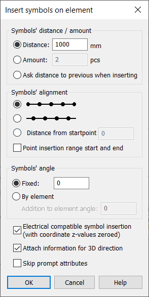
Define the symbol insertion settings:
-
Symbols' distance / amount:
-
Distance – Insert the symbols to the element with the desired space between them. The number of inserted symbols depends on the length of the element and the distance given.
-
Amount – Insert the desired number of symbols to elements evenly spaced. The distance between elements depends on the length of the element and number of symbols inserted.
-
Ask distance to previous when inserting – Select this if you want the distance to the previous symbol to be asked for each symbol separately.
-
-
Symbols' alignment:
-
With the first alignment option, you can insert symbols to the ends of the element and the rest evenly spaced along the element.
-
With the second alignment option, you can leave an empty space to both ends of the element (0.5 x distance between symbols) and insert the rest with even spaces.
-
Distance from startpoint – You can determine from which point the insertion of symbols will begin.
-
Point insertion range start and end – Select this if you want to insert the symbols only to some part of the element.
-
-
Symbol's angle:
-
Fixed – All symbols will be inserted to given angle.
-
By element – Symbols will be added to angle equal to elements tangent angle in insertion point. With Addition to element angle, the given angle will be added to the angle determined by previous settings.
-
-
Electrical compatible symbol insertion – If selected, symbols Z-position will be zeroed during insertion. Otherwise Z-position will be determined by elements Z-position at symbols insertion point.
-
Attach information for 3D direction – Select this if you want to set 3D direction attributes for 3D generation. This ensures that the generated 3D symbols will be inserted with the same angle.
-
Skip prompt attributes – Select this if you do not want the application to ask for prompt attribute values for inserted symbols.
-
-
Click OK.
-
Indicate the element to which you want to insert the symbols. The Select elevation from the selected object dialog opens.
-
Select whether to take the elevation from the top, middle, bottom or based on the value you define.