Schematics tab > Devices group > ![]() Connectors menu > Insert terminal block / connector
Connectors menu > Insert terminal block / connector
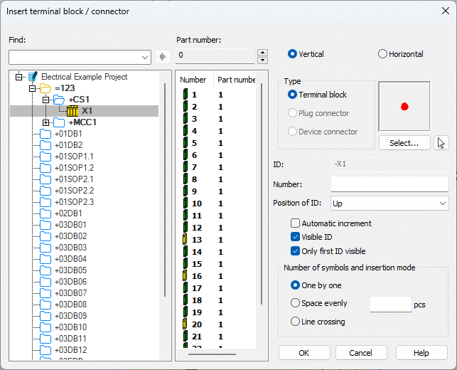
With this function, you can insert terminal blocks and plug and device connectors into drawings.
The insert dialog also opens when you select to insert a terminal symbol via the Symbols window.
Do the following:
- Define the terminal block or connector details:
- Select Vertical or Horizontal as the symbol direction.
- Type – Select the connector type:
Terminal block, Plug
connector or Device connector. Then select how you want to add the symbol:
- If you want to select the symbol from the current drawing, click the
 (Select from drawing) button and select the symbol in the drawing.
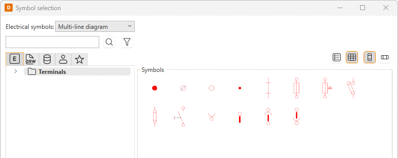
 - If you want to select the symbol in the Symbol selection dialog (see Symbol selection), click Select. Double-click the symbol to select it, or select the symbol and click OK.
- If you want to select the symbol from the current drawing, click the
- ID – Connector ID, for example, X1. ID can be typed or selected from the tree.
- Number – A number of the connector. If multiple connectors will be inserted, number of the first connector. The number can also be selected from the list.
- Position of ID – Position of ID and connector number in relation to the connector. With this option, it is possible to move texts away from the wire when inserting a connector vertically, for example.
- Automatic increment – If you select to insert terminal blocks one by one, you can decide whether to use incremental numbering. If you do not select this, you will be asked to define the number separately for each terminal block. When terminal blocks are inserted evenly or with line crossing, incremental numbering is used automatically.
- Visible ID – Show connector ID in a drawing.
- Only first ID visible – When inserting multiple connectors, show ID only in the first connector.
- Number of symbols and insertion
mode:
One by one – Insert connectors one by one. Define the number of connectors in the pcs field. The number will be incremented after every insertion.
Space evenly – Insert connectors evenly spaced: insert the first connector and then the second with the desired distance and direction. The function will insert the rest of the connectors accordingly.
Line crossing – Draw a line across wirings, after which the function will insert connectors to every crossing between the wire and the line drawn.
Note: If you opened the insert dialog via the Symbols window, the type and the symbol are already defined based on the selected symbol and therefore disabled.


-
Click OK.
-
Indicate the insertion point. A reference point of ID and connector number can be changed during insertion with the TAB key.
You can also insert terminal blocks / connectors from the same terminal strip by right-clicking the desired terminal block / connector or terminal strip and selecting Insert terminal blocks of this strip in drawing. Then define the details as described above.