Release notes
CADMATIC software has two main releases annually. The release name identifies the publishing year, the half (H1 or H2), and possible patch update designation (R2 or higher). These release notes describe new features, improvements, and bug fixes made in software version 2025H2 and its patch updates.
Release notes for CADMATIC Draw are available here.
Previous CADMATIC Electrical release notes:
New features and improvements in 2025H2
This software release contains the following new features and improvements.
|
Toolset |
Category |
Description |
||||||||||||||
|---|---|---|---|---|---|---|---|---|---|---|---|---|---|---|---|---|
|
All |
Integrations |
In the Enterprise solution, it is now possible to define an integration between CADMATIC Electrical and CADMATIC Wave. A document request for Electrical can be created in Wave to predefine the required documentation that needs to be sent to Wave. Electrical receives the request, and a document can be linked to the request with its metadata. When the document is ready, it can be sent to the Wave document management system. New document revisions can also be requested, and they are automatically linked to the previous versions. After the required changes are done, a new document revision can be sent back to Wave. This feature requires a license. |
||||||||||||||
|
All |
Languages |
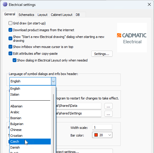
A technical upgrade in the background enables better support for multiple languages that are now available in the application. The locale and language settings affect as follows:
The user interface changes related to languages are explained in detail in these release notes. |
||||||||||||||
|
All |
Languages |
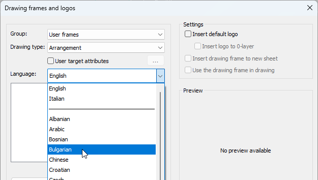
Several new languages are available in all the functions (such as drawing frame and label management, drawing frame change, saving customer drawings
|
||||||||||||||
|
All |
Product models |
In the Product models tree, you can now see the number of product model devices in the active drawing and the number of all product model devices (1/2, for example). |
||||||||||||||
|
All |
Product models |
When inserting a product model via the project tree (with the Insert one by one function, for example), it is now possible to add a symbol suitable for the active drawing type if it is missing. The missing product model information is then filled with information coming from the selected symbol after which the symbol can be inserted. |
||||||||||||||
|
All |
Product models |
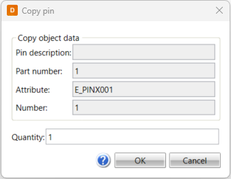
In the product model property dialog, it is now possible to copy product model pins via the Pins tab by right-clicking the desired pin and selecting Copy. The number and attribute values get running numbers; for example, if the attribute of the pin is E_PINB001, the copied pin attribute will be E_PINB002.
|
||||||||||||||
|
All |
Product models |
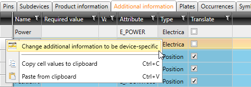
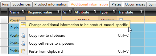
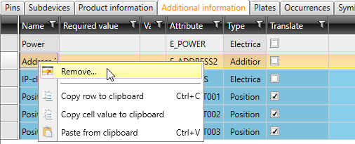
In device properties, on the Additional information tab, the Copy additional information to object function has been changed as follows:
The Change additional information to be device-specific and Remove functions are also available in the product model properties. In both cases, the piece of additional information is removed from the product model. |
||||||||||||||
|
All |
Product models |
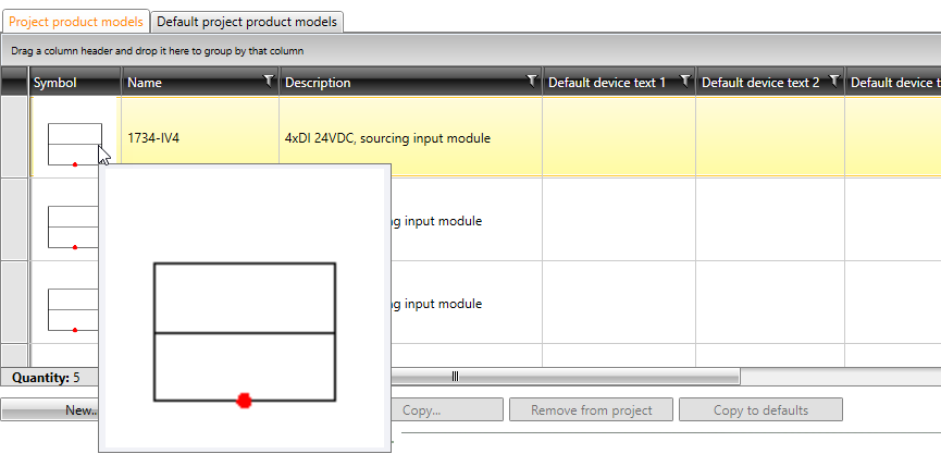
In Product model management, on the Project product models tab, you can now see the icon of the first symbol in the product model. When hovering over the icon, a bigger image of the symbol is shown.
|
||||||||||||||
|
All |
Product models |
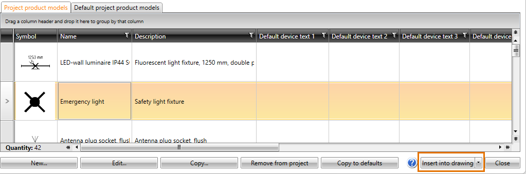
It is now possible to insert a symbol into a drawing in Product model management.
|
||||||||||||||
|
All |
Product models |
EDZ import has been improved: The application now checks that the macro to be imported is supported. If it is not supported or import fails for some other reason, the user is notified. |
||||||||||||||
|
All |
Reports |
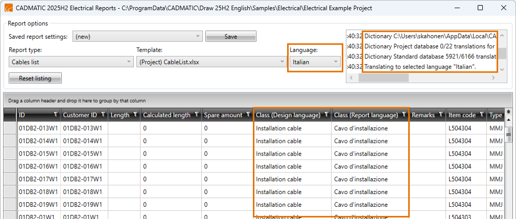
If something else than the design language is selected as the report language, it is possible to show two different columns – design language and report language – for the translated columns. The status section shows how many translations were found.
|
||||||||||||||
|
All |
Settings |
In the Common section of project settings, the following new options are available:
|
||||||||||||||
|
All |
Settings |
In the general Electrical settings, the Symbol descriptions in user interfaces settings has been changed as follows:
|
||||||||||||||
|
All |
Symbols |
The order of the tabs in the Symbol selection dialog has been changed. The order is now the following:
|
||||||||||||||
|
All |
Symbols |
The order of the tabs in the Symbols window has been changed. The order is now the following:
|
||||||||||||||
|
All |
Symbols |
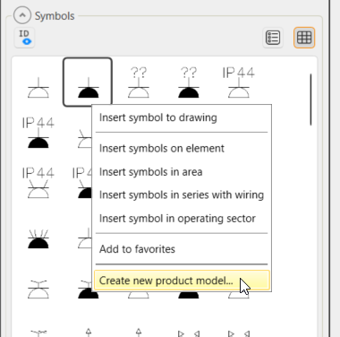
In the Symbols window, it is now possible to create a product model based on the selected symbol (except for distribution board tables).
The new product model will get the 2D and 3D symbols and the device type from the selected symbol. |
||||||||||||||
|
All |
Symbols |
When the program finds a conflict which prevents using a symbol although it exists in the application and the database, there is a new right-click menu function, Clean database symbols with faulty path information, available in the Symbols window, on the
|
||||||||||||||
|
All |
Symbols |
Saving your own symbols has been changed as follows:
|
||||||||||||||
|
Single-line |
Distribution boards and groups |
The user is now notified if more than one feeder feeds a device as that is not yet supported in electrotechnical calculations. |
||||||||||||||
|
Single-line |
Project tree |
The Insert an occurrence of this device into drawing and Insert device text to the drawing functions are now available in the Product models and Storeys and spaces project trees. |
||||||||||||||
|
Single-line, Layout |
Network |
Network calculation has been changed as follows:
|
||||||||||||||
|
Layout |
Cableways |
Drawing cableways has been changed as follows:
|
||||||||||||||
|
Layout |
Holes |
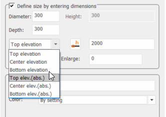
When defining or editing holes, you can now select the elevation to be absolute top, center or bottom elevation.
|
||||||||||||||
|
Layout |
Holes |
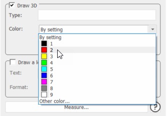
You can now define the 3D hole color.
|
||||||||||||||
|
Layout |
IFC |
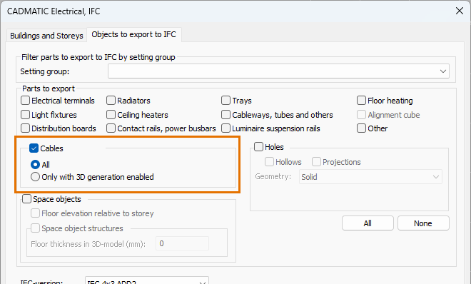
Cables are now supported in IFC export. Cable types provide a default value for a new setting that determines whether cables are exported to the IFC file, but users can change the setting for individual cables later.
|
||||||||||||||
|
Layout |
IFC |
There is now support for creating custom property sets for cables, allowing users to include any cable data they wish in the generated IFC file. |
||||||||||||||
|
Layout |
Light fixtures |
The DIALux functions have been changed as follows:
|
||||||||||||||
|
Layout |
Light fixtures |
When re-importing light fixtures from DIALux, new product models are created only when required i.e. if the product code has changed. |
||||||||||||||
|
Layout |
Product models |
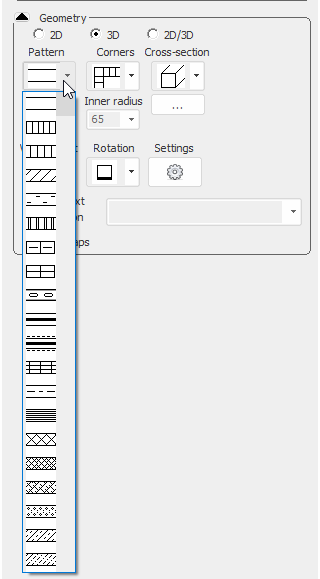
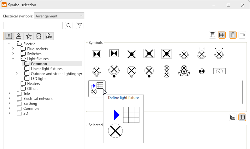
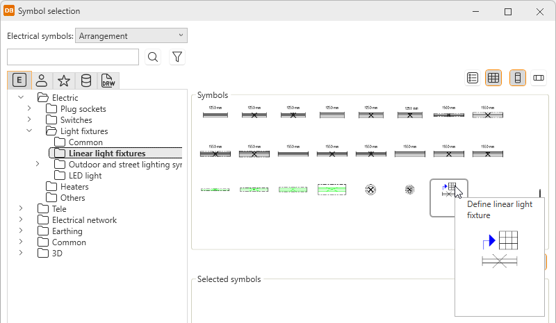
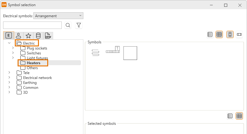
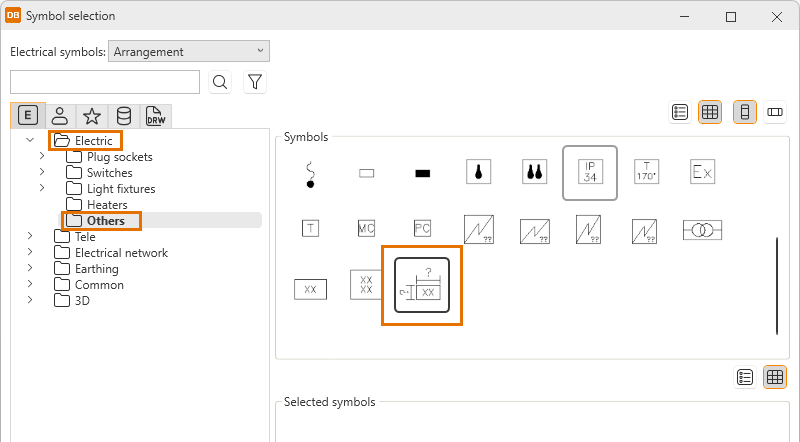
A scalable symbol, two new heater symbols and definition of a light fixture and linear light fixture are now available in the Symbol selection dialog to be used with product models. You can define the information in the same way as when inserting the symbols. The information defined will be saved as product model properties.
|
||||||||||||||
|
Layout |
Product models |
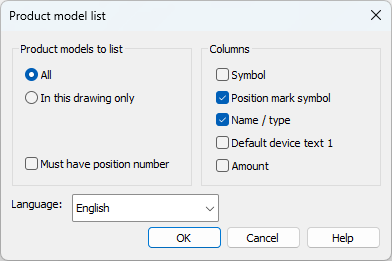
The Product models and Positions project tree functions List of project's product models into drawing and List of folder's product models into drawing have been changed: In the Product model list dialog, it is now possible to select the language into which Name / type and Default device text 1 are translated. By default, the design language is used. If no translation is found, the original value is used.
|
||||||||||||||
| Layout |
Spaces |
The Space dialog has been changed as follows:
|
||||||||||||||
| Layout |
Spaces |
Editing the general data of several spaces has been changed as follows:
|
||||||||||||||
|
Layout |
Storeys |
It is now possible to define storey boundaries to include more than one storey in one arrangement document.
|
||||||||||||||
|
Layout |
Symbols |
In the Insert symbols on element, Insert symbols in area, Insert symbols in series with wiring, and Insert symbol in operating sector functions, you can now also select the symbol by indicating it in the drawing. |
||||||||||||||
|
Layout |
Symbols |
Instead of the old icon menus, the following functions now also use the Symbol selection dialog for selecting the symbols:
|
||||||||||||||
|
Layout |
Symbols |
When a device symbol has the 3D equivalence defined and the device is assigned to a product model, the 3D information is removed from the symbol. |
||||||||||||||
|
Layout |
Wiring |
IDs given to cable package cables in different functions were not properly checked which resulted in the same ID assigned for multiple cables. |
||||||||||||||
|
Schematics |
Symbols |
Instead of the old icon menu, the Wire > User wire markings function now also uses the Symbol selection dialog for selecting the symbol. |
||||||||||||||
|
DB |
Additional information |
ID attributes starting with E_PIN and F_PIN have been reserved for system use and they cannot be defined as additional information attributes. |
||||||||||||||
|
DB |
Additional information |
The ETIM database has been updated. |
||||||||||||||
|
DB |
Cables |
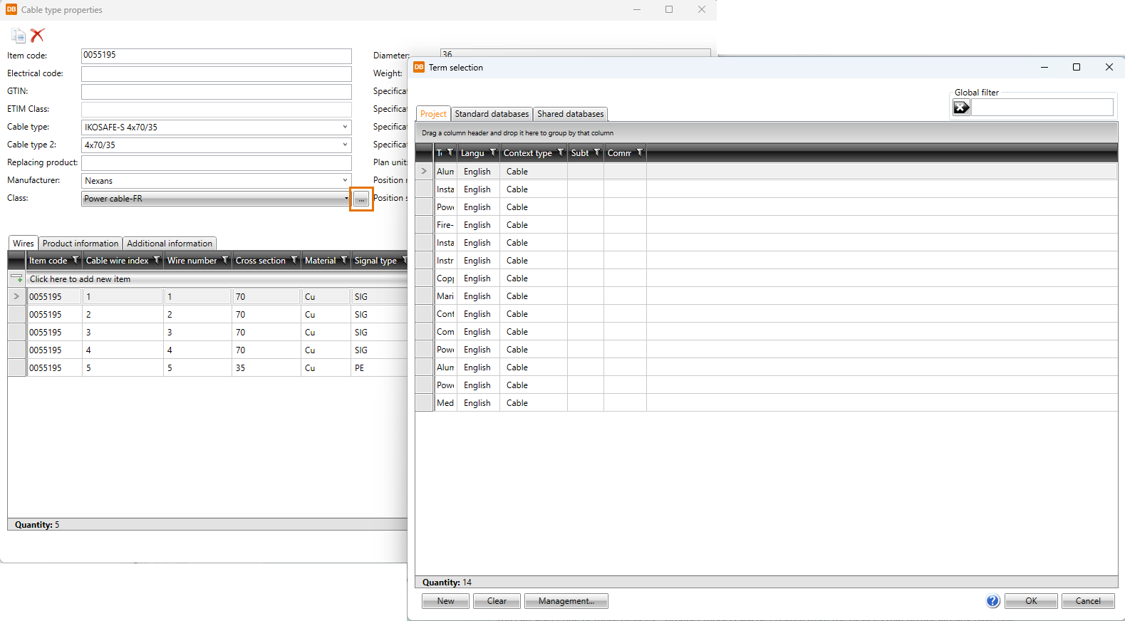
In Cable type properties, the language drop-down menu next to the Class field has been removed. Instead, the
|
||||||||||||||
|
DB |
Distribution boards |
The IFC type column is now available on the Distribution boards tab. |
||||||||||||||
|
DB |
Grids |
Instead of a color code, wire colors are now shown in full in the various grids. The change affects, for example, the Wires and Cables tabs and cable type management. |
||||||||||||||
|
DB |
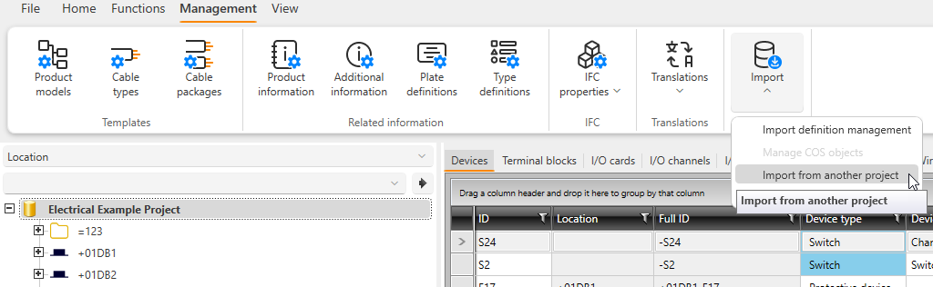
Imports |
Import functions have been moved from the Functions tab to the Management tab:
|
||||||||||||||
|
DB |
Product information |
|
||||||||||||||
|
DB |
Product models |
It is now possible to create product models via the Devices grid.
|
||||||||||||||
|
DB |
Settings |
The settings have been changed as follows:
|
||||||||||||||
|
DB |
Translations |
The various translation functions have been changed as follows:
|

New features and improvements in 2025H2R2
This software release contains the following new features and improvements.
|
Toolset |
Category |
Description |
|---|---|---|
|
All |
Product models |
In product model properties, it is now possible to update the symbol icon with the Update icon function.
This function is not available when the property dialog is opened via the DB tool. |
Bug fixes in 2025H2
This software release contains the following bug fixes.
|
Toolset |
Category |
Description |
|---|---|---|
|
All |
Documents |
When creating a new drawing, the application suggested a drawing type not included in the user's license. |
|
All |
Product models |
Despite the Update devices automatically option being enabled, pins were not updated when several devices were inserted. |
|
All |
Product models |
When a symbol included in a product model was replaced with another symbol by the same name and also replaced in the drawing, it was not replaced in the product model. |
|
All |
Product models |
In product model properties, it was no longer possible to add ETIM data. |
|
All |
Product models |
When a device was copied, the ID format used was taken from the device instead of the product model. |
|
All |
Product models |
When default folders were used for product models, the folder and the device type changed when the symbol was replaced with another. |
|
All |
Settings |
In Electrical settings, on the DB tab, the Use project database setting did not work. The setting is unnecessary and has been removed. |
|
All |
Symbols |
In device and product model properties, it was not possible to replace symbols on the Symbols tab. |
|
All |
Symbols |
The Symbols window and Symbol selection dialog did not always show symbols correctly. |
|
All |
Symbols |
Symbol packages were not always saved correctly. |
|
Single-line |
Distribution board tables |
Sometimes the drawing did not match the database. |
|
Single-line |
Distribution board tables |
Wiring references did not work as should in distribution board drawings. |
|
Single-line |
Symbols |
The Assign symbols in drawing to this device function did not work correctly when an occurrence with a symbol package was selected. |
|
Single-line |
Symbols |
In load diagrams, unnecessary feeders were sometimes created when inserting symbols. |
|
Layout |
Boundaries |
The update function in the External references window did not take into account the space information of modified space boundaries. |
|
Layout |
Boundaries |
When creating an additional information boundary, the default system was always used instead of the system user had selected. |
|
Layout |
Boundaries |
When updating reference drawings, additional information was only updated for devices with no product model. |
|
Layout |
Cables |
Some cables were removed when the drawing was opened. |
|
Layout |
Distribution boards |
In the Insert object info to drawing dialog, Input, Cable and Cable package were not shown for distribution boards. |
|
Layout |
Distribution boards |
When the distribution board's insertion elevation was changed, the elevation in the drawing was changed to 0. Furthermore, moving the distribution board sometimes changed the insertion elevation to 0. |
|
Layout |
Drawings |
Checking of symbol type and generation of icons for the symbols resulted in slowness when opening the drawing. |
|
Layout |
IFC |
Exporting more than project simultaneously in different instances resulted in an error. |
|
Layout |
IFC |
Selecting Alignment cube when exporting IFC resulted in an error. |
|
Layout |
IFC |
Additional information defined for distribution boards was not exported. |
|
Layout |
IFC |
Some elements in an inactive drawing were not included in the export. |
|
Layout |
Labels |
Logo was only shown correctly in a label when the scale of the drawing was 1:1. |
|
Layout |
Labels |
If a custom label was used, revisions were not handled correctly. |
|
Layout |
Markings |
It was possible to define customer location in a drawing that was not in a project. |
|
Layout |
Product models |
After changing the product model 3D symbol, 3D generation did not take the change into account. |
|
Layout |
Product models |
If product information's 3D symbol was changed on a product model, 3D generation was only done after synching the drawing and the database. |
|
Layout |
Settings |
The Unpaired references project setting did not work as should. |
|
Layout |
Storeys |
Cableways did not always receive storey information. |
|
Layout |
Storeys |
In IFC export, values were rounded when the site was far from the origo. |
|
Layout |
Systems |
In the System selection dialog, it was not possible to select the system by picking it from the drawing. |
|
Schematics |
Cables |
If a cable was removed before removing the last occurrence, the cable was not removed from the feeder. |
|
Schematics |
Connectors |
When inserting device connectors, filtering the available ones did not work as should. |
|
Schematics |
Copying |
When copying elements, some temporary attributes were saved. |
|
Schematics |
Copying |
Incorrect IDs were used when copying multilayer terminal blocks. |
|
Schematics |
Customer drawings |
When saving customer drawings, wrong information was saved instead of the drawing name. |
|
Schematics |
Frames |
The drawing frame with columns by sheets was scaled correctly only in size A3. |
|
Schematics |
Frames |
User's own frames were not saved into the symbol directory defined in the general settings. |
|
Schematics |
I/Os |
When creating I/O cards, the handling of channels was not taken into account. |
|
Schematics |
I/Os |
Wiring references were generated for I/O card symbols. |
|
Schematics |
Markings |
Internal wire number was not shown in the drawing if the Cable Customer ID visibility in drawing project setting was set to Visible. |
|
Schematics |
Wiring |
When changing the wire color while wiring and then continuing in another drawing, the color in the other drawing did not change accordingly. |
|
Schematics |
Wiring |
Pins were not moved with cable termination wires. |
|
Schematics |
Wiring |
The Draw wire of the cable function started to draw wires for a new cable instead of the selected one. |
|
Cabinet Layout |
Modes |
Right-clicking in the project tree caused the mode to change from print to layout. |
|
DB |
Devices |
On the Devices tab, it was not possible to edit product model device's description. |
|
DB |
Distribution boards |
The feeding distribution board and/or group were not always shown correctly for distribution boards. |
|
DB |
Documents |
When sorting documents, Cabinet layout and Cabinet Layout were handled as different directories and the sorting was done incorrectly. |
|
DB |
Import |
Some of the functions were sometimes hidden when the size of different sections in the import definition dialog were changed. |
|
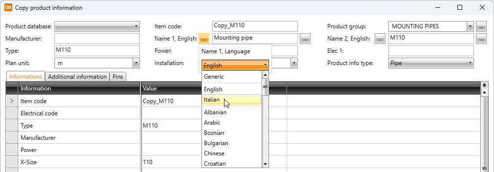
DB |
Import |
When importing product information, the column headers were not always shown in the application language. |
|
DB |
Product models |
EDZ import failed without error messages or warnings. |
|
DB |
Product models |
Importing product models from SQL resulted in an error. |
|
DB |
Reports |
When Use prefix visibility settings in reports had been enabled in project settings, the prefix was sometimes shown incorrectly in some reports. |
|
DB |
Reports |
In SQLite projects, some circuit IDs were handled incorrectly, resulting in an error when creating reports. |
|
DB |
Reports |
In some reports, the name of additional information was shown instead of the additional information value. |
|
DB |
Reports |
Sums were not calculated correctly in heater and lighting fixture reports. |
|
DB |
Product information |
Adding product information from the standard database to the shared database via the right-click menu resulted in an error. |
|
DB |
Wires |
In the Wire properties dialog, clicking OK without making any changes resulted in an incorrect notification about missing information. |
Bug fixes in 2025H2R2
This software release contains the following bug fixes.
|
Toolset |
Category |
Description |
|---|---|---|
|
All |
Settings |
After visiting the project default settings without making any changes, editing the drawing resulted in an error. |
|
All |
IDs |
The ID format defined for type definitions and product models required using prefixes and suffixes. |
|
Layout |
IFC |
A missing hollow subtype caused an error in IFC export and resulted in a faulty IFC file. |
|
Layout |
Storeys |
The absolute elevation preview did not take storey boundaries into account. |
|
Layout |
Symbols |
In the Symbols window, the Import symbols from user icon menus function did not show the OK and Cancel buttons in the selection dialog and it was not possible to import any menus. |
|
Layout |
Symbols |
Moving an occurrence sometimes crashed the application. |
|
Layout |
Symbols |
Importing user's own symbols from icon menus sometimes resulted in an error if there were symbols with the same name. |
|
Layout |
Symbols |
It was not possible to define 3D equivalence for a product model occurrence in a drawing not included in a project. |
|
Schematics |
Connectors |
Inserting terminal strips and terminal blocks via the Devices tree did not always work as should. |
|
Schematics |
I/Os |
The address prefix column did not update automatically in product model properties. |
|
Schematics |
Sheets |
In sheet management, copying and pasting information from one sheet to another sometimes resulted in an error. |
|
Single-line, Schematics |
Wiring |
In the Draw busbars dialog, the Crossing wires option did not work as should. The option has been removed, and wire crossing is now always set on. |
|
Cabinet Layout |
Devices |
It was not always possible to insert devices because of missing default symbols. |
|
Cabinet Layout |
Symbols |
Running IDs did not work properly when inserting several scalable symbols. |
|
DB |
Databases |
Checking the location of the EDBUserCommon database at startup did not work as should. In addition, if the database was not found, the default location database was not taken into use. |
|
DB |
Databases |
Converting the database when opening a drawing not in a project sometimes resulted in an error. |
|
DB |
Databases |
When copying previous version's files, the SQLite database file was not created if the user's operating system did not recognize the file extension. As a result, the EDBUserData file was not created either. |
|
DB |
Import |
In product model management, importing information from older versions was not always possible. |
|
DB |
Product models |
In shared databases, editing I/O product model's pins resulted in an error. |
|
DB |
Product models |
Changing product model symbol's part number resulted in an error. |
Bug fixes in 2025H2R4
This software release contains the following bug fixes:
|
Toolset |
Category |
Description |
|---|---|---|
|
All |
Devices |
In the Device properties dialog, selecting a plate sometimes resulted in an error. |
|
All |
Devices |
The ID was incorrectly assigned in the symbol insertion dialog. |
|
All |
Revisions |
When adding several revision markings, the function did not remember the given initials. |
|
Single-line |
Symbols |
It was not possible to insert distribution board symbol packages via the Symbol selection dialog. |
|
Layout |
Boundaries |
When adding an additional information boundary, it was not always possible to create a new boundary type. |
|
Layout |
Cableways |
Cableway length was sometimes calculated wrong for the marking. |
|
Layout |
Positions |
Some heater and lighting fixture types were left out when calculating heater and light fixture positions. |
| Schematics | Frames | Defining the default frame in the Drawing frames and logos dialog did not work. |
| Schematics | Frames | When user created a frame based on an existing file, it was saved to the wrong location and hence was not available. |
| Schematics | Product models | Using the Product models project tree function Create a new terminal block from product model and insert its symbol resulted in an error before insertion. |
|
Schematics |
Wiring |
The Extend wire function cleared user's snap definitions. |
|
Schematics |
Wiring |
When defining wiring references, the Stay on target sheet option did not work. |
| Schematics |
Wiring |
Cable termination shield was drawn incorrectly. |
| Cabinet Layout | Symbols | A device occurrence with a scalable symbol was not assigned an ID nor size information when inserted. |
|
DB |
Additional information |
On the Devices tab, an additional information value entered in a cell was replaced with the default value defined in the additional information definition. |
|
DB |
Cables |
Cable classes were not shown correctly. |
|
DB |
Documents |
Grouping did not work because the selected column header was added to the grouping row twice. |
|
DB |
IFC |
When creating IFC property selection definitions to a shared database, it was not possible to select IFC property sets. |
|
DB |
Import |
Importing a template project resulted in an error. |
|
DB |
Import |
Importing cable types resulted in an error. |