Release notes
CADMATIC software has two main releases annually. The release name identifies the publishing year, the half (H1 or H2), and possible patch update designation (R2 or higher). These release notes describe new features, improvements, and bug fixes made in software version 2025H1 and its patch updates.
Release notes for CADMATIC Draw are available here.
Previous CADMATIC Electrical release notes:
New features and improvements in 2025H1
This software release contains the following new features and improvements.
|
Toolset |
Category |
Description |
||||||||||
|---|---|---|---|---|---|---|---|---|---|---|---|---|
|
All |
Projects |
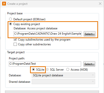
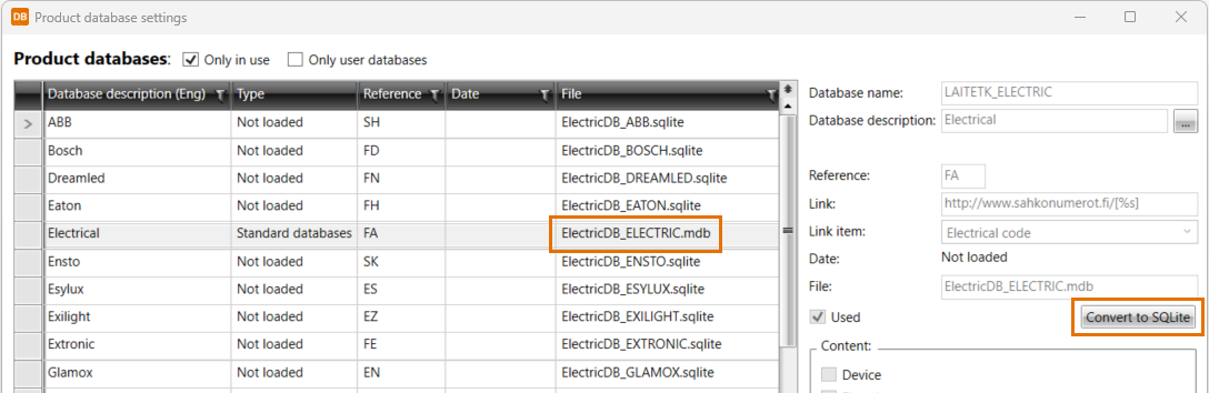
We have introduced a new database format called SQLite. Compared to MDB, it is faster and smoother as unexpected third-party updates will no longer interrupt usage. However, it is still possible to use the old MDB projects as well.
|
||||||||||
|
All |
If the project database has been set as read-only, the top level of the project tree shows the following icons:
|
|||||||||||
|
All |
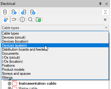
The objects in the drop-down menu are now in alphabetical order:
|
|||||||||||
|
All |
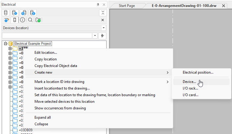
The project tree has been changed as follows:
|
|||||||||||
|
All |
In the Product models tree, it is now possible to copy a product model by right-clicking and selecting Copy product model. |
|||||||||||
|
All |
The following new tabs are available in project settings:
|
|||||||||||
|
All |
In the Common section in project settings, a new option, IFC version, is available. The version-specific values (types, properties, property sets, etc.) are shown in the application based on this setting. In IFC export, it is possible to select the IFC version – if it differs from the version selected here, the user will be notified as that version might not include all the needed values. |
|||||||||||
|
All |
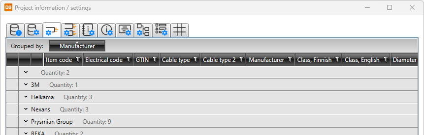
In project settings, it is now possible to group information on all tabs with grids.
|
|||||||||||
|
All |
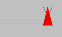
In project settings, there are now separate unpaired cross-reference settings for diagrams and arrangement drawings: Unpaired cross-references (Diagrams) and Unpaired cross-references (Arrangement drawings). A new option, Do not mark, is available for both. This option allows you to keep the unpaired reference in the drawing but not mark it with a cross:
|
|||||||||||
|
All |
New design languages have been added into the project settings. The project language affects the project’s wiring color abbreviations, default frame, and symbol descriptions, for example. |
|||||||||||
|
All |
In general settings, the Start correct application, if drawing type is defined setting has been removed as it is no longer possible to change the sub-application (Schematics, Layout, etc.) manually; all functions of the sub-applications have been merged into one Electrical application, and the correct ribbon tab and functions are shown automatically based on the drawing type. |
|||||||||||
|
All |
In general settings, there is a new Symbol descriptions in user interfaces setting available. The user can select application's language or design language as the language in which the symbol descriptions are shown. If the description is not found in that language, the other option is used. If the description is not found at all, the description will be empty. |
|||||||||||
|
All |
Symbols |
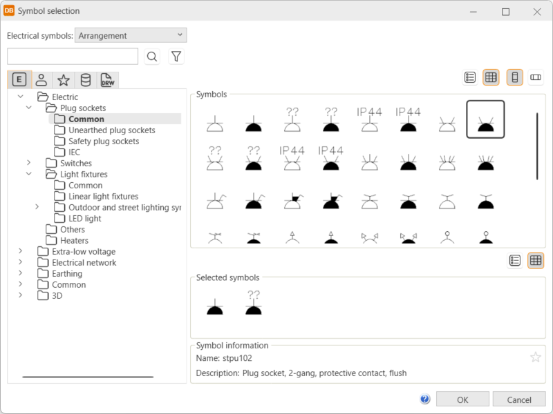
Instead of the icon menus, symbols will now be selected in the new Symbol selection dialog in all functions.
The new dialog will open, for example, when
|
||||||||||
|
All |
Symbols |
The Symbols window has been changed as follows:
For more information, see the following instructions:
|
||||||||||
|
All |
Symbols |
Saving user's own symbols has been changed as follows:
For more information, see the following instructions:
|
||||||||||
|
Layout |
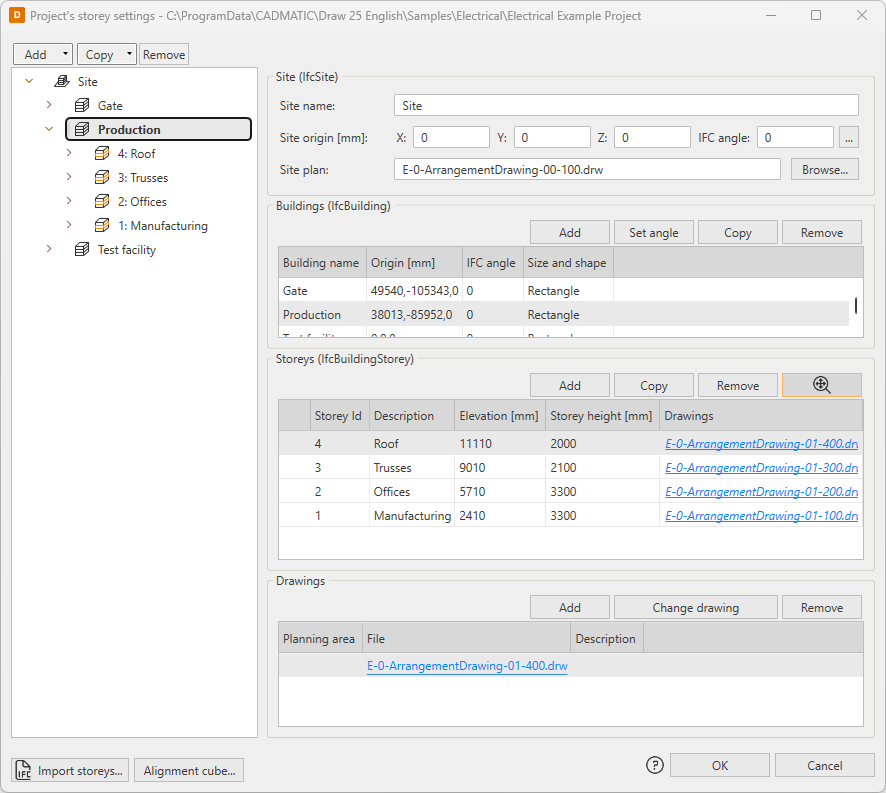
The storey settings have been changed as follows:
|
|||||||||||
|
Layout |
Symbols |
The
|
||||||||||
|
Layout |
When starting the Leader to element's markings layer function via the right-click menu, the selected object's system and layer are now used. |
|||||||||||
|
Layout |
Distribution board and group management has been changed as follows:
|
|||||||||||
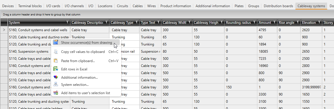
| Layout | Cableways |
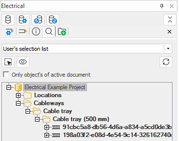
You can now add cableways to user's selection list.
|
||||||||||
|
Layout |
Boundaries |
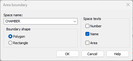
It is now possible to define number, name and/or area to be shown for area boundaries. Previously, the name was always shown.
|
||||||||||
|
Layout |
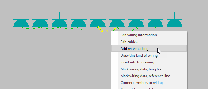
By default, wire marking is not added for short wires (10x scale) – now, it is possible to add the wire mark later with the Wire marking (automatic) function or by right-clicking the wire and selecting Add wire marking.
When a short wire is selected, the application will confirm if you want to add the marking. If you selected several wires, you can select Yes to insert the marking to all the selected wires whereas No will skip the short ones and only insert it to the longer ones. |
|||||||||||
|
Layout |
On the Hole functions tab, the Other hole symbols button now opens the Symbols window instead of the symbol menu, offering an easier way to insert provision symbols. |
|||||||||||
|
Layout |
It is now possible to divide the space also by right-clicking the space wall and selecting Divide space. |
|||||||||||
|
Layout |
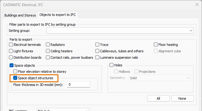
IFC |
IFC functions have been changed as follows:
|
||||||||||
|
Layout, Single-line |
Network |
Network calculation has been changed as follows:
|
||||||||||
|
Single-line |
In the Distribution boards and groups project tree, the Draw wiring into drawing function is now available for feeder's cable packages. |
|||||||||||
|
Single-line |
Distribution boards |
In distribution board tables, it is now possible to insert object information by right-clicking the object and selecting Insert object info to drawing. |
||||||||||
|
Layout, Schematics |
Integrations |
It is now possible to export cableways to CADMATIC Plant Modeller with the MDL export function. In addition to the MDL file, a CSV file with a description for each part is saved to enable mapping the parts in Plant Modeller. |
||||||||||
|
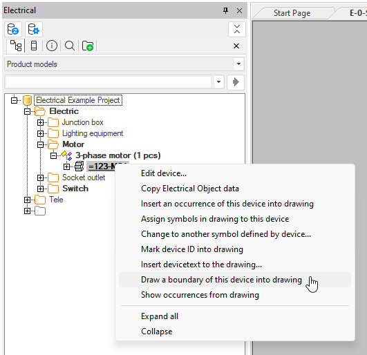
Single-line, Schematics |
Product models |
For single-line diagrams, load diagrams and multi-line diagrams, there is a new option in the right-click menu of the Product models project tree: Draw a boundary of this device into drawing.
|
||||||||||
|
DB |
The Ask again about speed optimization in large projects option has been removed from File > Settings. |
|||||||||||
|
DB |
Symbols |
It is now possible to add symbols via the property dialogs.
For more information on symbol selection, see Symbol selection. |
||||||||||
|
DB |
Grids |
On the
|
||||||||||
|
DB |
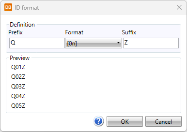
Devices |
It is now possible to define the desired device ID format for product models and type definitions, for example. With prefix, format and suffix, it is possible to generate the IDs according to your own preferences.
|
||||||||||
|
DB |
Product models have been changed as follows:
|
|||||||||||
|
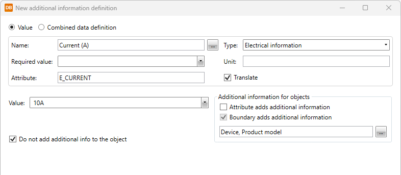
DB |
It is now possible to display any data from the project database directly in the drawings using preset definitions. These combined data definitions ensure key project data is always visible, consistent, and clearly documented. Combined data definitions can be created via the same dialog as new additional information. The layout of the New additional information definition dialog has been changed because of the new feature.
|
|||||||||||
|
DB |
The ETIM database has been updated. |
|||||||||||
|
DB |
The Cableway systems tab has been changed as follows:
|
|||||||||||
|
DB |
IFC |
On the Management tab, there is now a new IFC properties drop-down menu from which you can select the following:
With these functions you can define the IFC properties in the database and add them to the property sets, after which you can create selection definitions to be used when exporting IFC files from Electrical. |
||||||||||
|
DB |
In the SQL Server project management dialog, all the buttons have been replaced with new ones. |

New features and improvements in 2025H1R3
|
Toolset |
Category |
Description |
|---|---|---|
|
DB |
SQL |
On the Projects tab, the Access projects group has been renamed as Local projects and it now also shows SQLite projects. |
Bug fixes in 2025H1
This software release contains the following bug fixes.
|
Toolset |
Category |
Description |
|---|---|---|
|
All |
Installation |
When opening Electrical for the first time after installation, all the menus were not included. |
|
All |
Projects |
In SQL server project management, grouping, sorting and filtering criteria were not saved when closing the dialog. |
|
All |
Symbols |
In the Symbols window, the symbol preview was shown incorrectly when the symbol included text. |
|
All |
Revisions |
User rights did not work correctly with the revision functions. |
|
All |
Distribution boards |
In Distribution board and group management, the Wiring field was empty for cable packages. |
|
Layout |
Setting files |
In Setting files management, the Close and update drawing function did not work as should. |
|
Layout |
Labels |
If there was no frame/label in the design language, the default frame/label inserting function did not insert anything. Now, if there is no frame/label in the design language the frame/label will be inserted according to the user interface language (English or Finnish). |
|
Layout |
Devices |
When moving a LED strip, the ID attribute did not move. |
|
Layout |
Symbols |
The running ID was not set on and off correctly. |
|
Layout |
Symbols |
When editing user's own symbol, a new symbol was created instead. |
|
Layout |
Symbols |
The Cabling to rectangular area and Cabling to polygon area heater functions did not remember the previous settings if the functions were started right after the previous use. |
|
Layout |
Markings |
Changing the Cable Customer ID visibility in drawing project setting was not updated to the drawing before closing and opening it again. Furthermore, the ID did not update at all for cable wire marks. |
|
Layout |
Markings |
When copying a marking with storey information, the storey was not updated. |
|
Layout |
Copying |
When copying group marks, new ID was not suggested for protective devices as for the group marks. |
|
Layout |
Wiring |
When wiring had been started from a distribution board, changing the wiring style resulted in an error. |
|
Layout |
Wiring |
When cable creation was started from a tree view, the new cable did not always get the class information from the selected cable type. |
|
Layout |
Cableways |
When leaving cableway edit without making any changes, filter was always left on. |
|
Layout |
Cableways |
The cableway references were handled incorrectly when opening a drawing. |
|
Layout |
Cableways |
Elevation was shown incorrectly when negative. |
|
Layout |
Cableways |
When printed, vertical cableways did not follow user settings. |
|
Layout |
Distribution boards and groups |
Inserting a group mark activated insertion of symbols next to each other. |
|
Layout |
Distribution boards and groups |
It was not possible to rotate a distribution board with F8 before indicating the insertion point. |
|
Layout |
Quantity calculation |
The length of cables in a cable package were calculated incorrectly with metric unit. |
|
Layout |
Boundaries |
When creating new additional info boundary types, system was not always set right. |
|
Layout |
3D |
The Automatically add symbol to 3D device group when inserting left of right setting did not take the maximum symbol width into account and therefore inserted symbols incorrectly. |
|
Layout |
3D |
The |
|
Layout |
3D |
IFC export resulted in an error when there were 3D objects in the drawing. |
|
Layout |
Auxiliary functions |
In print mode, a sticker added via the auxiliary functions was of wrong size. |
|
Single-line |
Distribution boards |
The Import groups data to manufacturers distribution board schema function was missing from the ribbon. It is now available on the Distribution Board tab, in the Auxiliary functions drop-down menu. |
|
Single-line |
Distribution boards |
After removing a distribution board symbol in distribution board properties, a random symbol was added automatically. |
|
Schematics |
Frames |
When the drawing was not in a project, inserting the default frame did not follow the design language. |
|
Schematics |
Sheets |
Changing sheets with the Page up ad Page down keys was slow when there were locked layers. |
|
Schematics |
Sheets |
Changing the sheet via the drop-down menu on the ribbon did not work if there were empty sheets in the drawing. |
|
Schematics |
Symbols |
Creating a user symbol via the Symbols toolbar did not work correctly. |
|
Schematics |
Symbols |
I/O symbols were inserted based on the device GUID and part number which sometimes resulted into the symbol being replaced by another one with the same part number. |
|
Schematics |
Devices |
In a drawing included in a project, connector's symbols and pin numbers were changed when the drawing was opened. |
|
Schematics |
Wiring |
If the cable was drawn through connection points, a new cable was not created after the cable was cut. |
|
Schematics |
Wiring |
When using wiring mark user symbols converted from an earlier version, the E_ID attribute was shown for wiring marks and it was not possible to hide it. |
|
Schematics |
Wiring |
Adding or copying a cable marking when the project setting Cable Customer ID visibility in drawing was set to Visible resulted in the information not updating immediately into the drawing. |
|
Schematics |
Wiring |
When removing cable termination references, reference occurrences sometimes stayed in the run-time database causing problems when redrawing. |
|
Schematics |
Cables |
The project tree was not always updated when removing cables or cable packages. |
|
Schematics |
Markings |
When a drawing was opened without the project database, all the cable markings were moved to the active layer. |
|
Schematics |
References |
When references were on different sheets and drawing the reference was canceled, the first part of the reference stayed in memory, causing problems when using the function next time. |
|
Schematics |
References |
When editing a drawing made in a version released prior to 2020, it was not possible to change the angle of upward or downward reference arrows to 0. |
|
Schematics |
References |
References were added for busbars when adding references from terminal strips to devices and from devices to devices. |
|
Schematics |
Connectors |
When drawing terminal strips or inserting terminal blocks, numbers and part numbers were not always completely shown. |
|
Schematics |
Additional information |
The Additional information function showed all project's additional information as selected. |
|
Schematics |
Boundaries |
Description that was removed from a location boundary when edited was shown again when the drawing was saved and reopened. |
|
Schematics |
Customer drawings |
Saving in DWG and moving sheets next to each other did not work as should. |
|
Cabinet Layout |
Symbols |
When inserting a symbol, the symbol defined for the device was not used. |
|
DB |
Project tree |
If the database was set as read-only, the drawing was interpreted as not in project. Now, if the project database is read-only the drawing will also be opened as read-only. |
|
DB |
Grids |
Settings made in grids did not always work correctly. |
|
DB |
Cables |
Opening a project resulted in an error when missing cable types were created for cables. |
|
DB |
Product information |
Whether product information links were shown or not depended on the locale setting. |
|
DB |
Product information |
Product information's additional information values were not copied from the standard or the shared database to the project database. |
|
DB |
Additional information |
ETIM data was not updated without closing and reopening the product information. |
|
DB |
I/Os |
When creating a new I/O card with manufacturer and address 0, the I/O channels were locked. |
|
DB |
I/Os |
Filtering I/O channels via the project tree did not work. |
|
DB |
Modular generation |
Modular generation got slow when done several times in a row. |
|
DB |
Reports |
When creating reports, it was not possible to filter reports out. |
|
DB |
SQL |
Opening a read-only project resulted in an error message that should have been a notification instead. |
Bug fixes in 2025H1R2
This software release contains the following bug fixes.
|
Toolset |
Category |
Description |
|---|---|---|
|
All |
Frames and labels |
When creating a user frame in some other than the application's language, the language was not saved correctly. |
|
All |
Symbols |
When selecting a distribution board symbol for a device in the Symbol selection dialog, no symbols were shown. |
|
Layout |
Symbols |
Attributes were inserted incorrectly when the symbol angle was 180 or 270°. |
|
Layout |
Symbols |
Attributes for a device inserted into a drawing were locked incorrectly when the drawing was not in a project. |
|
Layout |
Distribution boards and groups |
Selecting a protective device in the New group dialog did not work as should. |
|
Layout |
Distribution boards and groups |
When a group had several feeders and an individual feeder was edited, changes were not always saved to the database. |
|
Layout |
Cableways |
Cableways were not shown correctly when very low values had been used when scaling the drawing. |
|
Layout |
Lists |
The list of electrical symbols did not show user symbol descriptions. |
|
Layout |
3D |
3D generation of a polygon shaped floor heating drawn with the border line only did not work. |
|
Layout |
Product models |
Changes made in the Project product models dialog sometimes resulted in the application crashing. |
|
Layout |
Product models |
Additional information added for a product model sometimes resulted in the application crashing. |
|
Layout |
IFC |
Some IFC property types did not work in IFC export. |
|
Layout |
IFC |
Cableways of type Other were not exported. |
|
Layout |
IFC |
The Include Cadmatic Electrical property set setting did not work. |
|
Layout |
IFC |
Combined data definition's additional information was not exported. |
|
Single-line |
Symbols |
The function for inserting feeder symbols was missing from the Distribution boards and groups project tree. |
|
Single-line |
Busbars |
Running numbers were not assigned correctly for busbars that were created automatically. |
|
Single-line |
Distribution board tables |
The Symbol selection dialog did not always show symbols correctly. |
|
Single-line |
Distribution board tables |
When copying items in distribution board edit, all the related information was not copied. |
|
Schematics |
Symbols |
In the Symbols window, importing symbols from the old menus did not work as should. |
|
Schematics |
Markings |
Some characters used in attribute regex rule prefixes and suffixes were handled incorrectly, which resulted in an error when the drawing was opened again. |
|
Schematics |
Wiring |
Canceling the redraw function resulted in the application crashing. |
|
Schematics |
Terminal blocks |
In the Draw terminal strip dialog, creating, editing and deleting pins did not work. |
|
Schematics |
Reports |
Using specific special characters resulted in an error when creating a report. |
|
Cabinet Layout |
Product models |
When inserting a device via the product model, the ID was not suggested based on the symbol type. |
|
DB |
Additional information |
When additional information was defined for a device in the grid, the Do not add additional info to the object setting behaved differently than when defined via the device properties dialog. |
|
DB |
Product information |
Replacing product information resulted in the application crashing. |
|
DB |
Product information |
When editing product information, copying and pasting pins resulted in an error. |
|
DB |
Product information |
Loading product information databases was not possible. |
|
DB |
Product information |
Changing the item code resulted in an error. |
|
DB |
Product information |
On SQL Server, importing product information sometimes resulted in an error. |
|
DB |
IFC |
in the Type drop-down menu in the IFC property definition dialog, there was one type missing and one unnecessary type available. |
|
DB |
Reports |
Sums were calculated incorrectly for the Sum list of cable products report. |
|
DB |
SQL |
In SQL Server project management, there were filtering options that did not affect the filtering in that column. |
Bug fixes in 2025H1R3
This software release contains the following bug fixes.
|
Toolset |
Category |
Description |
|---|---|---|
|
All |
Product models |
When using product models, symbol preview did not always work as should. |
|
All |
Reports |
Updating a report via the project tree or using saved settings in the reporting tool sometimes resulted in an error. |
|
All |
Settings |
In project settings, the selected value was not shown in the Standard field. |
|
All |
Symbols |
In the Symbols window, user's own symbols were shown according to the active drawing's type instead of the type selected on the |
|
All |
Symbols |
The tooltip given for a user symbol was not used as the default device text for the device created. |
|
Schematics, Cabinet Layout |
Product models |
Creating a product model via the Product models project tree did not work as should: the type of the symbol selected in the Symbol selection dialog was wrong, and pins were created incorrectly. |
|
Single-line |
Distribution board tables |
Some distribution board symbols were missing from the Symbol selection dialog. |
|
Single-line |
Distribution board tables |
Feeder texts were not saved correctly. |
|
Layout |
Cables |
The Cable types project tree did not show cable length for all cables. |
|
Layout |
Calculations |
When listing objects with length, LED strips with length were not taken into account. |
|
Layout |
Calculations |
The List of cable position numbers into drawing function calculated cable length wrong when there were several cable occurrences in the same drawing. |
|
Layout |
Distribution boards |
In the Distribution boards and groups project tree, the Connect to a supplying distribution board function did not work if the target distribution board already existed with a defined cable. |
|
Layout |
IFC |
Updating the project IFC file resulted in user's property set definitions to disappear from the IFC model. |
|
Layout |
IFC |
IFC files imported with DIALux 13.1 or later did not work. |
|
Layout |
Light fixtures |
When several types of light fixtures had been selected, the Insert position markings function did not insert position marks for LED strips. |
|
Layout |
Locations |
In an Arrangement (not in scale) drawing, the wrong 3D default symbol was used for location boundaries and when creating a location from the label and defining a location for a device. Also, it was not possible to define the missing size and location information in connection with insertion. |
|
Layout |
Locations |
Space information did not update correctly for locations. |
|
Layout |
Reports |
In the light fixture list, positioned light fixtures were listed incorrectly when there were more than one occurrence of the same device in the drawing. |
|
Layout |
Symbols |
In an Arrangement (not in scale) type of drawing, it was not possible to change a symbol to another because the drawing type was not recognized. |
|
Layout |
Symbols |
The STPKESK4 and STPKESK9 symbols were missing from the Symbol selection dialog. |
|
Layout |
Symbols |
In the Symbols window, changes made on the |
|
Layout |
Symbols |
When selecting a 3D symbol for a scalable symbol, the symbols were shown incorrectly in the Symbol selection dialog. |
|
Layout |
Symbols |
ID format was missing from some data network symbols which resulted in them not getting an ID. |
|
Schematics |
Markings |
If the wiring reference special format included the pin description, the marking was formed incorrectly. |
|
Schematics |
Project tree |
The Positions project tree did not update correctly. |
|
Schematics |
Symbols |
An error in saving your own symbols removed user's rights to the user symbols. |
|
Schematics |
Symbols |
Changing the symbol direction for a user symbol did not work correctly. |
|
Schematics |
Symbols |
Creating symbols (relays, for example) via the old symbol menus did not work as should. |
|
Schematics |
Printing |
Queue printing resulted in the application crashing. |
|
Cabinet Layout |
IDs |
Assigning IDs and running the ID numbers did not always work as should. |
|
DB |
Additional information |
If the Attribute adds additional information setting was enabled, empty values were never updated for label's additional information when editing additional information definitions. |
|
DB |
Cables |
The Clear button in the Change To-information and Change From-information functions did not clear the information from the cables. |
|
DB |
Import |
Importing from another project resulted in an error. |
|
DB |
Modular generation |
Modular generation first resulted in an error and then the application crashing. |
|
DB |
Product models |
If a product model had plenty of occurrences, opening the drawing was slow. |
|
DB |
Product models |
In Product model properties, replacing a symbol by selecting from the drawing resulted in an error. |
|
DB |
Product models |
Product model pins were assigned the wrong parent type when pins were created in connection with selecting the symbol. |
|
DB |
Product models |
On the Import/Export tab, global filtering did not work as should. |
|
DB |
Product models |
When copying an imported product model to the shared databases, additional information was not copied. |
|
DB |
Product models |
Updating the sub-device types sometimes resulted in the application crashing. |
|
DB |
Reports |
Creating reports sometimes resulted in an error if the settings file was XML. |
|
DB |
Reports |
Numerical values were listed incorrectly when both grouping and sorting by column was used. |
|
DB |
SQL |
SQLite projects were not listed in SQL Server project management. |
|
DB |
Terminal blocks |
Creating terminal blocks and pins via the right-click menu resulted in an error. |
|
DB |
Wires |
Editing wire numbers did not work as should. |
|
DB |
Wires |
When connecting cables, terminal strips were not created for new terminal blocks if the wire being edited had an occurrence. |
Bug fixes in 2025H1R4
This release contains the following bug fixes:
|
Toolset |
Category |
Description |
|---|---|---|
|
All |
Licensing |
Due to changes in Microsoft Azure cloud services, the old TLS protocols 1.0 and 1.1 have been disabled. This change also affects CADMATIC software and might cause problems when installing applications or using a user-specific license. This software release contains support for TLS 1.2. This update fixes the issues mentioned above and ensures compatibility with Azure. Furthermore, TLS 1.2 enhances data security as the older protocols contained known vulnerabilities. |