When adding and editing devices, the properties available depend on the device type. For example, there are specific fields available for I/O cards and terminal blocks which are not shown for other device types.
When you edit an existing device, all the changes you make are updated in all occurrences of that device in the project.
Learn more:
Add and edit devices
Do the following:
-
Open the device property dialog in one of the following ways:
-
If you want to add a new device:
-
In the Electrical project tree, right-click and select Create new > Device.
-
In the DB tool project tree, right-click and select New > Device.
-
In DB tool, select the Devices tab, right-click in the grid and select New device.
-
-
If you want to edit an existing device:
-
In the Electrical project tree, right-click the desired device and select Edit device.
-
In Electrical DB, select the Devices tab, and double-click the first column on the desired row.
-
In Electrical DB, select the Devices tab. Then select the desired row, right-click and select Edit device.
-
Depending on the function you used, either the New device or the Device properties dialog opens.
-
-
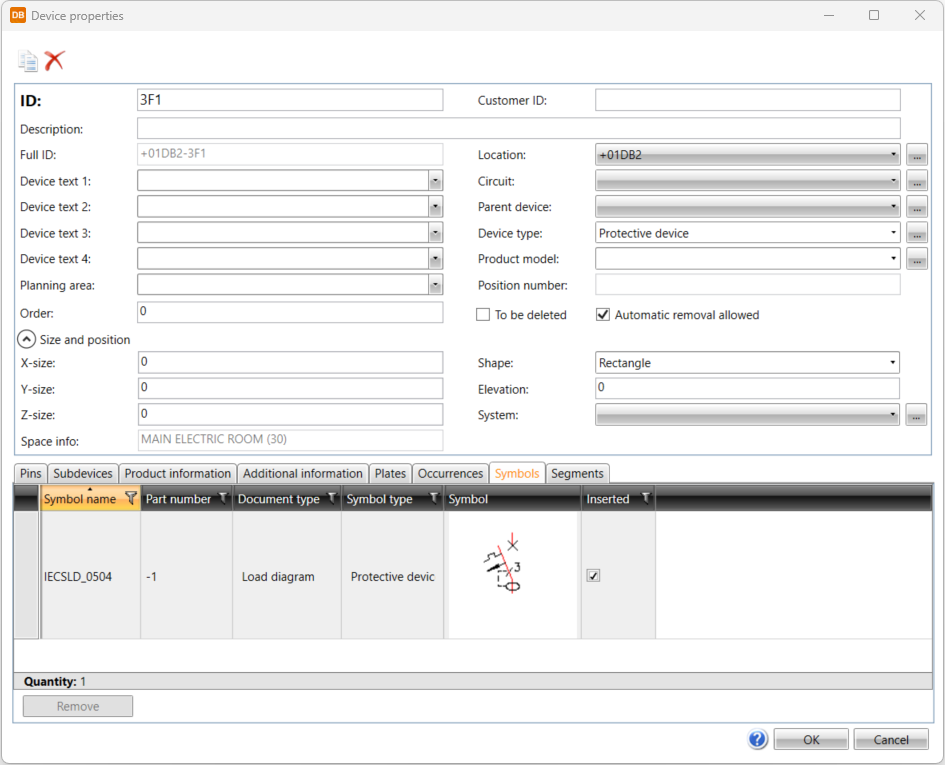
Edit the properties as necessary. Some of the properties available depend on the device type.
-
ID – Device ID
-
Customer ID – Optional, free-form ID for the device that can be displayed both in drawings and reports. For information on creating customer IDs, see Create customer IDs.
-
Description – Additional information about the device recorded in a report or a drawing.
-
Full ID – Full ID is constructed from location and device ID.
-
Device text 1–4 – Attributes of the device symbol in the drawing: E_SYMBTXT1–4. The texts can be edited in the drawing and the data will be updated in the database.
-
Planning area – Reports and grouping, for example, can have this piece of information as a filtering value.
-
Order
-
Location – Information about where the device is located.
-
Circuit – Additional information for the device.
-
I/O rack – Available when the device type is I/O card.
-
Parent device – If this is sub-device, displays next device on hierarchy.
-
Terminal strip – This is shown for terminal blocks.
-
I/O rack – This is shown for I/O cards.
-
Device type – Reports and grouping, for example can have this piece of information as a filtering value.
-
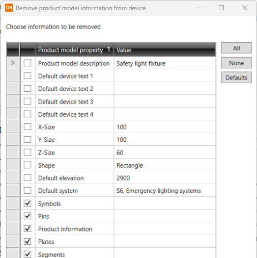
Product model – If a device has been assigned a product model, it will be displayed here. You can remove the product model from a device by selecting the empty option from the drop-down menu. The Remove product model information from device dialog opens and you can select the information you want to remove.
-
Position number – This is shown for devices that can be positioned.
- To be deleted – Mark the device as to be removed from the project database.
-
Automatic removal allowed – The device created from drawing can be deleted automatically.
-
Size and position
-
X-size, Y-size and Z-size – Dimensions of the device: width (X), height (Y) and depth (Z).
-
Space info – If device is located in some space.
-
Shape – Shapes define the 3D presentation of the device if 3D symbol is not defined.
-
Elevation – Elevation of the device in drawing. This affects for example 3D generation of the device.
-
System – System of the device.
-
The I/O card properties section is shown for I/O cards and other devices that have I/O card information. If the device type is something else than I/O card and the device has I/O card information, you can remove the information from the device by clicking the
 button in the I/O card properties section.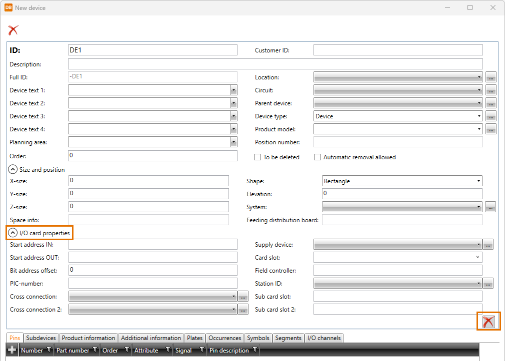
It is not possible to remove I/O card information from the I/O card itself. For more information on I/O cards, see I/O cards.
-
-
Define information on the various tabs as necessary.
 Pins
Pins
The Pins tab shows the device's pins (terminals) and their connections. Devices get pins from drawings and along with product information (item code) assigned to them. From a drawing, pins are created based on the wiring points of the device symbol occurrences. The wiring point refers to a terminal attribute, and together they form a pin. Several wiring points can be defined to the same terminal attribute, in which case they only form one pin.
The pins (wire connection points) are updated to the project database. You can edit pin values in the database. The values are updated to the device occurrences in drawings, where the pinGUID refers to the pin. The same pin can occur in several different symbols (occurrences) in the drawing.
If different symbols are used in different occurrences of the device and the symbols have the same attributes while they mean different things, you have to include a part number (e.g. [112]), which makes the pins different from each other.
Example of a complex contactor symbol
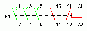
Attribute name: E_PINA001[112], Value: 1, Part number: 112
Attribute name: E_PINB001[112], Value: 2, Part number: 112
Attribute name: E_PINA001[114], Value: 3, Part number: 114
Attribute name: E_PINB001[114], Value: 4, Part number: 114
Attribute name: E_PINA001[116], Value: 5, etc.
Attribute name: E_PINB001[116], Value: 6
Attribute name: E_PINA001[202], Value: 13
Attribute name: E_PINB001[202], Value: 14
Attribute name: E_PINA001[201], Value: 21
Attribute name: E_PINB001[201], Value: 22
Attribute name: E_PINA001[101], Value: A1
Attribute name: E_PINB001[101], Value: A2
Part numbering
The part number is added to the pin attribute name in brackets for the compiled symbols e.g. E_PINA001[112].
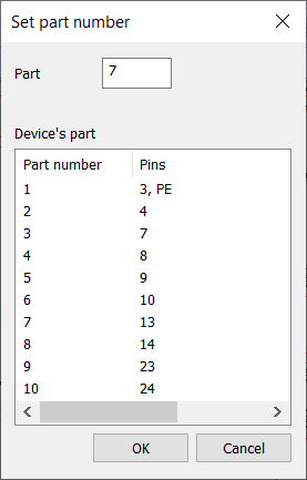
Part number is not visible in a single symbol occurrence but it can be seen/set by selecting the device, right-clicking and selecting Set part number.
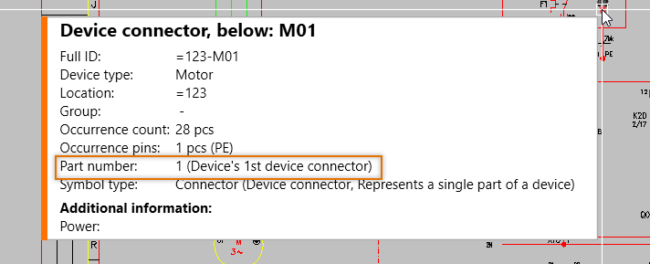
The part number is also shown in the information box:
Part number ranges
-
Feeds: 0
-
I/O channels: 0– (unlimited)
-
Plug-in terminals and device terminals: 1–99
-
Coils: 101–109
-
Main contacts:
-
Opening 111–199, odd numbers
-
Closing 112–198, even numbers
-
-
Auxiliary contacts:
-
Opening 201–299, odd numbers
-
Closing 202–298, even numbers
-
-
Contacts: 301–399
Add new pins
You can add new pins i.e. terminals to devices.
Do the following:
-
Click the
 button in the first column.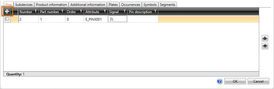
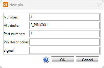
Alternatively, right-click and select New. The New pin dialog opens.
-
Define pin information:
- Number – Pin number, can also include letters, for example A1.
- Attribute – For every pin there is a corresponding attribute that includes pin number, for example E_PINA???, E_PINB??? or E_PINX??? according to the connection side.
- Part number – If different symbols are used in different occurrences of the device and the symbols have the same attributes while they mean different things, the part number (e.g. [112]) separates the pins from each other.
- Description – Optional free form description for the connection point.
- Signal – Optional signal type, e.g. SIG, N or PE.
- Click OK.
 Subdevices
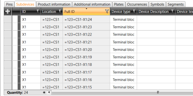
The Subdevices tab shows device's possible subdevices. For example, a terminal block is a subdevice of a terminal strip. Also another device inside the device boundary is shown as a subdevice of the device boundary.
 Product information
The Product information tab shows the product information attached to the device. In addition, you can select/edit the product information.
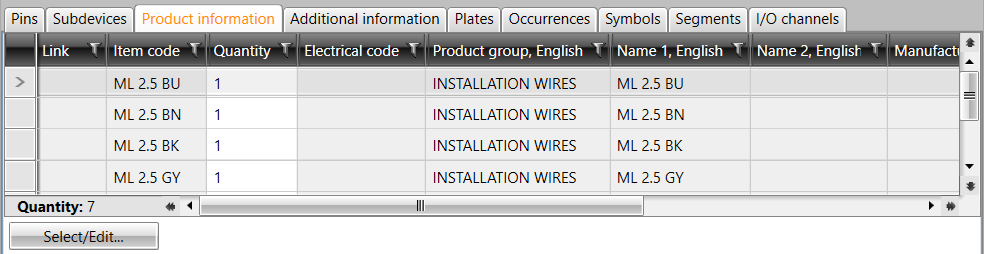
If an electrical number has been defined for the product, the Link column has a link to the Sahkonumerot.fi service.
Note: The Quantity value indicates how many pieces of product information one device has, not the total quantity of the product in the project.
Additional information
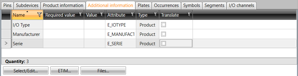
The Additional information tab shows details added for the device, such as descriptions, position texts and additional process information. This information can be displayed in drawings, and the information can also be edited from within the drawing.
On this tab, you can also select/edit the product information.
 Plates
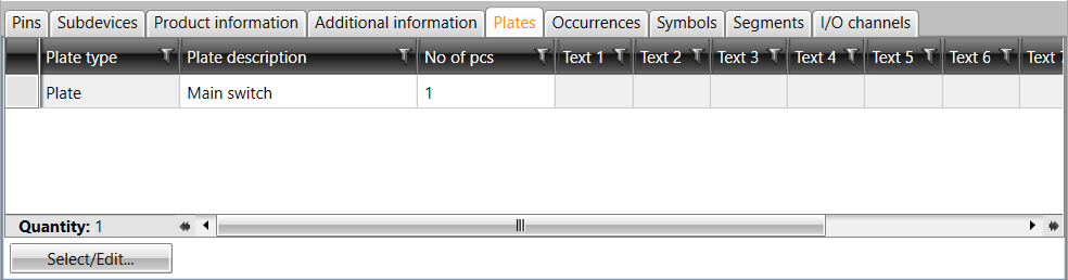
The Plates tab shows the plates attached to the device. In addition, you can select/edit the product information. A plate list can be run with the project's plates for production of the plates.
 Occurrences
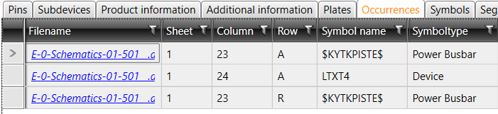
The Occurrences tab shows occurrences of the device, i.e. in which drawings the device has been used.
 Symbols
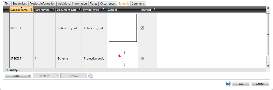
The Symbols tab shows which symbols are assigned to the device and whether they have been inserted into the drawing. On this tab, you can add symbols for the device before inserting an occurrence in the drawing.
-
After clicking the arrow next to Add, select whether to select the symbol from a menu, from 3D symbols, from a file, or from the drawing:
-
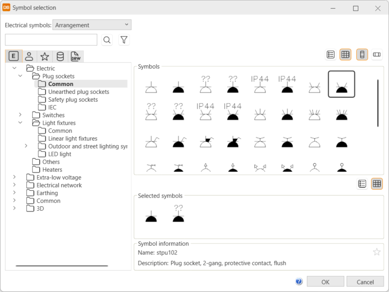
From menu – Select the desired symbol in the Symbol selection dialog.
Show/hide procedure
Do the following:
-
Select the desired tab:

Electrical symbols – This tab shows you all the Electrical symbols available.

User's symbols – This tab shows you the symbols you have saved with the Save user symbol function or imported from the user icon menus.

Favorite symbols – This tab shows you the symbols you have defined as your favorites.

Symbols in current project – This tab shows you all the symbols in the project.

Symbols in current drawing – This tab shows you the symbols that have been inserted in the active drawing.
-
Double-click the symbols you want to select. Alternatively, right-click them and select Add. The symbols are moved to the selected symbols.
-
Click OK. The symbols you selected are now shown on the Symbols tab.
For more information on the Symbol selection dialog, see Symbol selection.
You can also filter the symbols more by opening and selecting the tree nodes. In the Symbols section, symbols are shown according to your selection.
-
-
3D symbol – Select the desired 3D symbols in the Symbol selection dialog by double-clicking them and clicking OK. For more information on the Symbol selection dialog, see Symbol selection.
-
From drawing – Select the desired symbol in the drawing. This option is not available in the DB tool.
-
File – Select the document type, and then the symbol. This option is not available in the DB tool.
-
-
You can remove symbols that have not been inserted.
-
On the drawing side, you can replace symbols that have not been inserted. The type of the drawing affects replacing: If you are replacing a symbol of the same drawing type as that of the current drawing (single-line symbol / single-line diagram, for example), you have the option to select from the drawing or the menu, or a file. If you are replacing a symbol of a different drawing type (single-line symbol / arrangement drawing, for example), you can only select from the menu or a file.
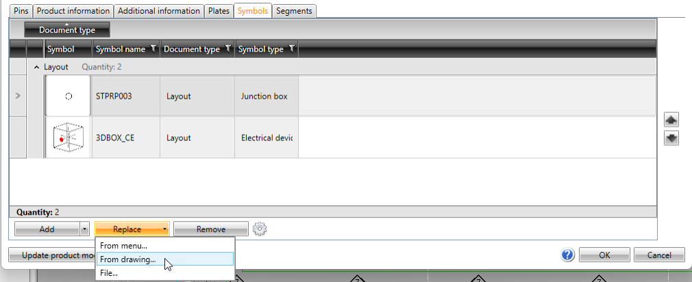
Replacing is not available in the DB tool.
-
Attributes and their values are read when selecting symbols. For the attributes that create additional information, you can click the
 button to define when to update or add additional information according to the symbol attributes. The object's text fields 1–4 are also updated according to the E_SYMBTXT 1–4 attributes.
The options for the setting are as follows:
-
Always – Additional information is always updated.
-
Never – Additional information is never updated.
-
Select – You can select the additional information you want to add/update. After selecting a symbol, the Update selected dialog opens and you can select what you want to update:
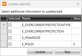
The addition/update is done according to your selection as long as you change the setting.
-
I/O channels
The I/O channels tab is available when the device type is I/O card or I/O rack.
You can add new I/O channels by clicking Add channels. In the Add channels dialog, define I/O channel information and click OK.
Feeders
The Feeders tab is available when the device type is Power busbar.
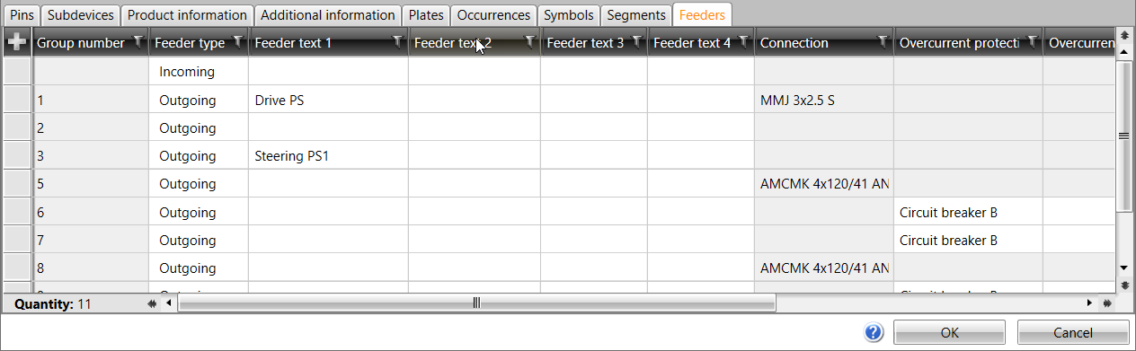
You can add new feeders by clicking the
button in the first column. Alternatively, right-click and select New.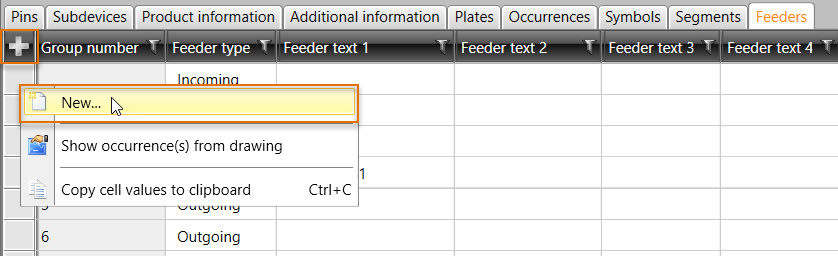
In the New group dialog, define feeder information and click OK. For more information, see Insert and edit feeders.
-
-
Click OK.
With the  (Copy) button, you can make a copy of the device. A new ID is then assigned for the new
device and production information, additional information, plates, etc. will
be copied. Pins are only copied from terminal strip subdevices i.e. terminal blocks. Occurrences and order will not be copied, nor the Automatic removal allowed setting.
(Copy) button, you can make a copy of the device. A new ID is then assigned for the new
device and production information, additional information, plates, etc. will
be copied. Pins are only copied from terminal strip subdevices i.e. terminal blocks. Occurrences and order will not be copied, nor the Automatic removal allowed setting.
You can cancel editing with the Cancel button, with the cross in the top right corner of the dialog, or with the Esc key.
In DB tool, when you select a device from the Electrical DB project tree, the device properties are shown on the Devices tab. You can edit the cells with white background right in the grid.
Delete devices
In the property dialog, you can delete the device from the database but not from the drawings with the (Remove) button.
The following two options affect deleting:
-
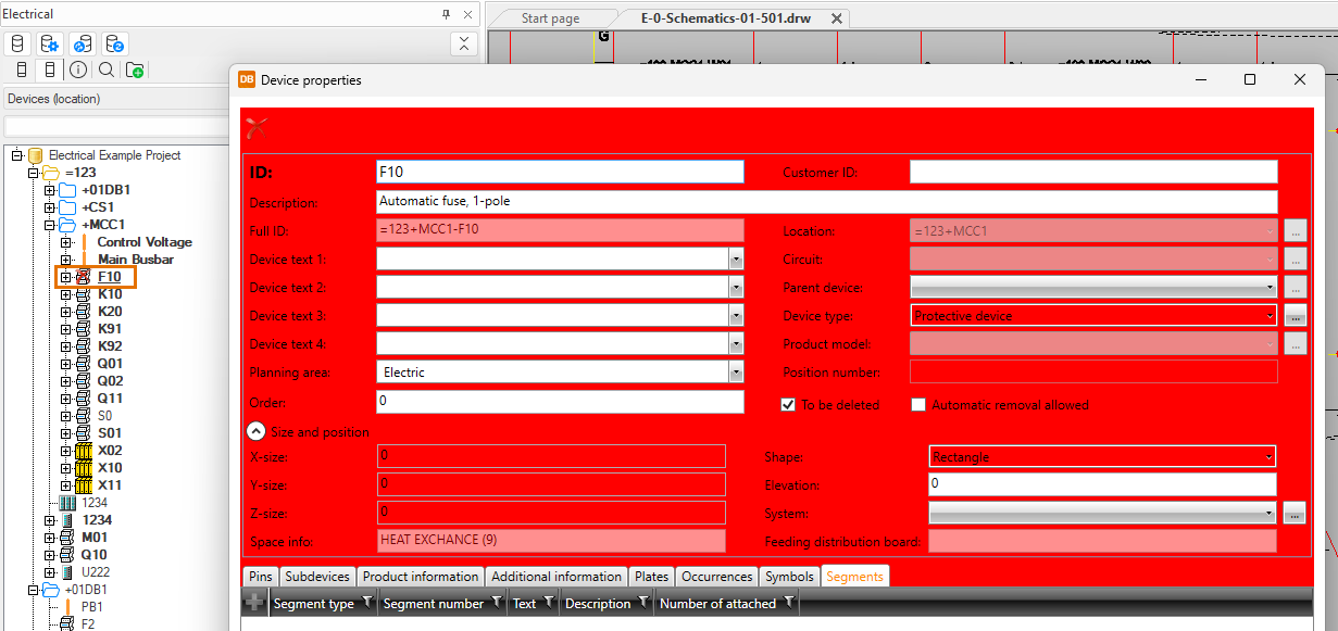
To be deleted – When you select this, the background turns red. When you close the dialog with OK, the tree also shows the device has been marked as to be deleted.
-
Automatic removal allowed – A device created via the drawing can be deleted automatically. A device created in the database is disabled.